Cirkit Designer Logo
Cirkit Designer
Your all-in-one circuit design IDE
Home / 
Component Documentation

How to Use Hall Effect: Examples, Pinouts, and Specs

Image of Hall Effect
Cirkit Designer LogoDesign with Hall Effect in Cirkit Designer

Introduction

A Hall Effect sensor is a device that detects the presence and strength of a magnetic field. It operates on the principle that a voltage is generated perpendicular to both the magnetic field and the current flow in a conductor. This property allows the sensor to measure magnetic fields and convert them into electrical signals. Hall Effect sensors are widely used in various applications, including:

  • Position sensing (e.g., detecting the position of a rotating shaft)
  • Current measurement in electrical circuits
  • Proximity sensing (e.g., detecting the presence of a magnet)
  • Speed detection in motors and wheels
  • Contactless switching in industrial and automotive systems

These sensors are valued for their reliability, durability, and ability to operate in harsh environments.

Explore Projects Built with Hall Effect

Use Cirkit Designer to design, explore, and prototype these projects online. Some projects support real-time simulation. Click "Open Project" to start designing instantly!
Magnetic Field-Activated Solenoid Array with Arduino Control
Image of Railgun: A project utilizing Hall Effect in a practical application
This circuit is designed to use Hall effect sensors for magnetic field detection, interfaced with an Arduino UNO microcontroller to control an array of solenoids through MOSFETs. It includes user interface elements such as a tactile switch and LED, and features flyback diodes for solenoid protection.
Cirkit Designer LogoOpen Project in Cirkit Designer
Arduino Nano 33 BLE Magnetic Levitation System with Hall Sensor Feedback and Status LED Indicator
Image of LEVITRON: A project utilizing Hall Effect in a practical application
This circuit is designed for a magnetic levitation system that uses a Hall sensor to detect magnetic field strength and a TIP120 transistor to control the current through a levitating coil. An Arduino Nano 33 BLE microcontroller reads the sensor and adjusts the coil current via PWM to maintain levitation, while an LED indicates the system's status. The circuit includes power management with 5V DC sources and protective components like diodes and resistors for current control and indication.
Cirkit Designer LogoOpen Project in Cirkit Designer
Arduino Nano-Based Propeller LED Pendulum Clock with Hall Sensor and Battery Power
Image of circuit diagram: A project utilizing Hall Effect in a practical application
This circuit features an Arduino Nano microcontroller interfaced with a Hall effect sensor and multiple LEDs of different colors, each paired with a resistor. The Arduino is programmed to act as a propeller LED pendulum clock, where the Hall sensor likely detects magnetic fields to synchronize the movement of the propeller, and the LEDs display time-related information. The code controls the lighting pattern of the LEDs to represent hours, minutes, and seconds, and allows for time adjustments via serial commands.
Cirkit Designer LogoOpen Project in Cirkit Designer
Arduino Nano ESP32 Hall Sensor Interface with LCD Display
Image of hall effect + speedometer: A project utilizing Hall Effect in a practical application
This circuit includes a Hall sensor connected to an Arduino Nano ESP32 microcontroller, which is likely used to detect magnetic fields and send the data to the microcontroller on pin D12. The Arduino is also interfaced with an LCD display, with connections for power, ground, control (RS, E), and data (DB4-DB7) to display information. The absence of code suggests that the microcontroller's behavior is not defined in this context, but it is set up to read the Hall sensor and output to the LCD.
Cirkit Designer LogoOpen Project in Cirkit Designer

Explore Projects Built with Hall Effect

Use Cirkit Designer to design, explore, and prototype these projects online. Some projects support real-time simulation. Click "Open Project" to start designing instantly!
Image of Railgun: A project utilizing Hall Effect in a practical application
Magnetic Field-Activated Solenoid Array with Arduino Control
This circuit is designed to use Hall effect sensors for magnetic field detection, interfaced with an Arduino UNO microcontroller to control an array of solenoids through MOSFETs. It includes user interface elements such as a tactile switch and LED, and features flyback diodes for solenoid protection.
Cirkit Designer LogoOpen Project in Cirkit Designer
Image of LEVITRON: A project utilizing Hall Effect in a practical application
Arduino Nano 33 BLE Magnetic Levitation System with Hall Sensor Feedback and Status LED Indicator
This circuit is designed for a magnetic levitation system that uses a Hall sensor to detect magnetic field strength and a TIP120 transistor to control the current through a levitating coil. An Arduino Nano 33 BLE microcontroller reads the sensor and adjusts the coil current via PWM to maintain levitation, while an LED indicates the system's status. The circuit includes power management with 5V DC sources and protective components like diodes and resistors for current control and indication.
Cirkit Designer LogoOpen Project in Cirkit Designer
Image of circuit diagram: A project utilizing Hall Effect in a practical application
Arduino Nano-Based Propeller LED Pendulum Clock with Hall Sensor and Battery Power
This circuit features an Arduino Nano microcontroller interfaced with a Hall effect sensor and multiple LEDs of different colors, each paired with a resistor. The Arduino is programmed to act as a propeller LED pendulum clock, where the Hall sensor likely detects magnetic fields to synchronize the movement of the propeller, and the LEDs display time-related information. The code controls the lighting pattern of the LEDs to represent hours, minutes, and seconds, and allows for time adjustments via serial commands.
Cirkit Designer LogoOpen Project in Cirkit Designer
Image of hall effect + speedometer: A project utilizing Hall Effect in a practical application
Arduino Nano ESP32 Hall Sensor Interface with LCD Display
This circuit includes a Hall sensor connected to an Arduino Nano ESP32 microcontroller, which is likely used to detect magnetic fields and send the data to the microcontroller on pin D12. The Arduino is also interfaced with an LCD display, with connections for power, ground, control (RS, E), and data (DB4-DB7) to display information. The absence of code suggests that the microcontroller's behavior is not defined in this context, but it is set up to read the Hall sensor and output to the LCD.
Cirkit Designer LogoOpen Project in Cirkit Designer

Technical Specifications

Below are the general technical specifications for a typical Hall Effect sensor. Note that specific models may vary, so always refer to the datasheet of the sensor you are using.

Key Technical Details

  • Operating Voltage: 3.3V to 24V (typical: 5V)
  • Output Type: Digital or Analog (depending on the model)
  • Current Consumption: 5mA to 15mA
  • Magnetic Sensitivity: 1 mT to 100 mT (varies by model)
  • Operating Temperature Range: -40°C to +125°C
  • Response Time: Typically less than 10 µs
  • Package Type: TO-92, SOT-23, or surface-mount packages

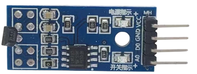
Pin Configuration and Descriptions

The pinout of a Hall Effect sensor depends on the specific model. Below is a common configuration for a 3-pin Hall Effect sensor (e.g., A3144):

Pin Number Name Description
1 VCC Power supply input (typically 3.3V or 5V)
2 GND Ground connection
3 OUT Output signal (digital or analog, depending on the sensor)

Usage Instructions

How to Use the Component in a Circuit

  1. Power the Sensor: Connect the VCC pin to a 3.3V or 5V power supply and the GND pin to the ground.
  2. Connect the Output: For a digital Hall Effect sensor, connect the OUT pin to a microcontroller's digital input pin. For an analog sensor, connect the OUT pin to an analog input pin.
  3. Place the Magnet: Position a magnet near the sensor. The sensor will detect the magnetic field and produce an output signal.
    • For a digital sensor, the output will typically be HIGH (logic 1) when no magnetic field is detected and LOW (logic 0) when a magnetic field is present.
    • For an analog sensor, the output voltage will vary proportionally to the strength of the magnetic field.

Important Considerations and Best Practices

  • Magnet Placement: Ensure the magnet is aligned correctly with the sensor's sensitive axis for accurate detection.
  • Debouncing: If using a digital Hall Effect sensor, consider implementing software debouncing to filter out noise in the output signal.
  • Pull-Up Resistor: Some digital Hall Effect sensors may require an external pull-up resistor on the output pin.
  • Magnetic Interference: Avoid placing the sensor near other magnetic sources that could interfere with its operation.
  • Temperature Effects: Be aware of the sensor's operating temperature range and ensure it is not exposed to extreme conditions.

Example Code for Arduino UNO

Below is an example of how to use a digital Hall Effect sensor (e.g., A3144) with an Arduino UNO:

// Define the pin connected to the Hall Effect sensor's output
const int hallSensorPin = 2; // Digital pin 2
const int ledPin = 13;       // Built-in LED pin

void setup() {
  pinMode(hallSensorPin, INPUT); // Set the sensor pin as input
  pinMode(ledPin, OUTPUT);       // Set the LED pin as output
  Serial.begin(9600);            // Initialize serial communication
}

void loop() {
  int sensorState = digitalRead(hallSensorPin); // Read the sensor's output
  
  if (sensorState == LOW) {
    // Magnetic field detected
    digitalWrite(ledPin, HIGH); // Turn on the LED
    Serial.println("Magnetic field detected!");
  } else {
    // No magnetic field detected
    digitalWrite(ledPin, LOW);  // Turn off the LED
    Serial.println("No magnetic field detected.");
  }
  
  delay(100); // Small delay for stability
}

Troubleshooting and FAQs

Common Issues and Solutions

  1. No Output Signal

    • Cause: Incorrect wiring or insufficient power supply.
    • Solution: Double-check the connections and ensure the sensor is powered with the correct voltage.
  2. Unstable or Noisy Output

    • Cause: Magnetic interference or lack of debouncing.
    • Solution: Move the sensor away from other magnetic sources and implement software debouncing.
  3. Sensor Not Detecting Magnetic Field

    • Cause: Magnet is too weak or improperly aligned.
    • Solution: Use a stronger magnet and ensure it is aligned with the sensor's sensitive axis.
  4. Output Always HIGH or LOW

    • Cause: Faulty sensor or incorrect pull-up resistor configuration.
    • Solution: Test the sensor with a different magnet and verify the pull-up resistor setup.

FAQs

Q: Can I use a Hall Effect sensor to measure current?
A: Yes, Hall Effect sensors are commonly used in current measurement applications. Specialized Hall Effect current sensors are designed for this purpose.

Q: What type of magnet should I use with a Hall Effect sensor?
A: Permanent magnets, such as neodymium or ferrite magnets, are commonly used. The strength and size of the magnet depend on the sensor's sensitivity.

Q: Can Hall Effect sensors detect non-magnetic materials?
A: No, Hall Effect sensors only detect magnetic fields and cannot sense non-magnetic materials.

Q: Are Hall Effect sensors affected by temperature?
A: Yes, extreme temperatures can affect the sensor's performance. Always operate the sensor within its specified temperature range.