Cirkit Designer Logo
Cirkit Designer
Your all-in-one circuit design IDE
Home / 
Component Documentation

How to Use RS485 to TTL Isolated: Examples, Pinouts, and Specs

Image of RS485 to TTL Isolated
Cirkit Designer LogoDesign with RS485 to TTL Isolated in Cirkit Designer

Introduction

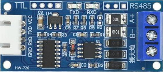
The RS485 to TTL Isolated converter is a versatile electronic component designed to facilitate communication between RS485 and TTL devices. It provides electrical isolation, which is crucial for protecting sensitive circuits from voltage spikes, ground loops, and other electrical disturbances. This isolation ensures reliable data transmission in industrial, automotive, and embedded systems.

Explore Projects Built with RS485 to TTL Isolated

Use Cirkit Designer to design, explore, and prototype these projects online. Some projects support real-time simulation. Click "Open Project" to start designing instantly!
ESP32-Based Industrial Control System with RS485 Communication and I2C Interface
Image of DRIVER TESTER : A project utilizing RS485 to TTL Isolated in a practical application
This circuit integrates a microcontroller with a display, digital potentiometer, IO expander, and opto-isolator board for signal interfacing and isolation. It includes a UART to RS485 converter for serial communication and a power converter to step down voltage for the system. The circuit is designed for control and communication in an isolated and protected environment.
Cirkit Designer LogoOpen Project in Cirkit Designer
Arduino UNO and Relay-Controlled RS485 Communication System
Image of Diagrama: A project utilizing RS485 to TTL Isolated in a practical application
This circuit features an Arduino UNO microcontroller interfaced with a 4-channel relay module and a UART TTL to RS485 converter. The Arduino controls the relays via digital pins and communicates with the RS485 converter for serial communication, enabling control of external devices and communication over long distances.
Cirkit Designer LogoOpen Project in Cirkit Designer
STM32 and Arduino UNO Based Dual RS485 Communication Interface
Image of STM to Arduino RS485: A project utilizing RS485 to TTL Isolated in a practical application
This circuit consists of two microcontrollers, an STM32F103C8T6 and an Arduino UNO, each interfaced with separate RS485 transceiver modules for serial communication. The STM32F103C8T6 controls the RE (Receiver Enable) and DE (Driver Enable) pins of one RS485 module to manage its operation, and communicates via the A9 and A10 pins for DI (Data Input) and RO (Receiver Output), respectively. The Arduino UNO is similarly connected to another RS485 module, with digital pins D2 and D3 interfacing with DI and RO, and D8 controlling both RE and DE. The RS485 modules are connected to each other through their A and B differential communication lines, enabling serial data exchange between the two microcontrollers over a robust and long-distance capable RS485 network.
Cirkit Designer LogoOpen Project in Cirkit Designer
RS485-Enabled NPK Soil Sensor Interface
Image of NPK: A project utilizing RS485 to TTL Isolated in a practical application
This circuit connects an NPK Soil Sensor to an RS485 transceiver module. The sensor's VCC and GND pins are connected to the corresponding VCC and GND pins on the RS485 module to provide power. The sensor's analog output (A) and digital output (B) are interfaced with the RS485 module's DI (Data Input) and DE (Driver Enable) pins, respectively, allowing the sensor's signals to be transmitted over an RS485 communication bus.
Cirkit Designer LogoOpen Project in Cirkit Designer

Explore Projects Built with RS485 to TTL Isolated

Use Cirkit Designer to design, explore, and prototype these projects online. Some projects support real-time simulation. Click "Open Project" to start designing instantly!
Image of DRIVER TESTER : A project utilizing RS485 to TTL Isolated in a practical application
ESP32-Based Industrial Control System with RS485 Communication and I2C Interface
This circuit integrates a microcontroller with a display, digital potentiometer, IO expander, and opto-isolator board for signal interfacing and isolation. It includes a UART to RS485 converter for serial communication and a power converter to step down voltage for the system. The circuit is designed for control and communication in an isolated and protected environment.
Cirkit Designer LogoOpen Project in Cirkit Designer
Image of Diagrama: A project utilizing RS485 to TTL Isolated in a practical application
Arduino UNO and Relay-Controlled RS485 Communication System
This circuit features an Arduino UNO microcontroller interfaced with a 4-channel relay module and a UART TTL to RS485 converter. The Arduino controls the relays via digital pins and communicates with the RS485 converter for serial communication, enabling control of external devices and communication over long distances.
Cirkit Designer LogoOpen Project in Cirkit Designer
Image of STM to Arduino RS485: A project utilizing RS485 to TTL Isolated in a practical application
STM32 and Arduino UNO Based Dual RS485 Communication Interface
This circuit consists of two microcontrollers, an STM32F103C8T6 and an Arduino UNO, each interfaced with separate RS485 transceiver modules for serial communication. The STM32F103C8T6 controls the RE (Receiver Enable) and DE (Driver Enable) pins of one RS485 module to manage its operation, and communicates via the A9 and A10 pins for DI (Data Input) and RO (Receiver Output), respectively. The Arduino UNO is similarly connected to another RS485 module, with digital pins D2 and D3 interfacing with DI and RO, and D8 controlling both RE and DE. The RS485 modules are connected to each other through their A and B differential communication lines, enabling serial data exchange between the two microcontrollers over a robust and long-distance capable RS485 network.
Cirkit Designer LogoOpen Project in Cirkit Designer
Image of NPK: A project utilizing RS485 to TTL Isolated in a practical application
RS485-Enabled NPK Soil Sensor Interface
This circuit connects an NPK Soil Sensor to an RS485 transceiver module. The sensor's VCC and GND pins are connected to the corresponding VCC and GND pins on the RS485 module to provide power. The sensor's analog output (A) and digital output (B) are interfaced with the RS485 module's DI (Data Input) and DE (Driver Enable) pins, respectively, allowing the sensor's signals to be transmitted over an RS485 communication bus.
Cirkit Designer LogoOpen Project in Cirkit Designer

Common Applications and Use Cases

  • Industrial automation and control systems
  • Communication between microcontrollers and RS485 devices
  • Long-distance data transmission in noisy environments
  • Protection of sensitive circuits in harsh electrical conditions
  • Integration of RS485-based sensors and actuators with TTL-based microcontrollers

Technical Specifications

Key Technical Details

  • Input Voltage (VCC): 3.3V to 5V DC
  • RS485 Communication Standard: Half-duplex
  • TTL Logic Levels: Compatible with 3.3V and 5V systems
  • Isolation Voltage: Up to 2500V
  • Baud Rate: Up to 115200 bps
  • Operating Temperature Range: -40°C to 85°C
  • Dimensions: Typically compact, varies by manufacturer

Pin Configuration and Descriptions

The RS485 to TTL Isolated module typically has the following pinout:

Pin Name Direction Description
VCC Input Power supply input (3.3V to 5V DC).
GND - Ground connection.
TXD Input TTL transmit data (from microcontroller to RS485).
RXD Output TTL receive data (from RS485 to microcontroller).
A (D+) Bidirectional RS485 differential signal positive (D+).
B (D-) Bidirectional RS485 differential signal negative (D-).
ISO GND - Isolated ground for RS485 side.

Note: Pin names and configurations may vary slightly depending on the manufacturer. Always refer to the specific datasheet for your module.

Usage Instructions

How to Use the Component in a Circuit

  1. Power the Module:

    • Connect the VCC pin to a 3.3V or 5V power source, depending on your system.
    • Connect the GND pin to the ground of your microcontroller or power supply.
  2. Connect TTL Signals:

    • Connect the TXD pin of the module to the RX pin of your microcontroller.
    • Connect the RXD pin of the module to the TX pin of your microcontroller.
  3. Connect RS485 Signals:

    • Connect the A (D+) and B (D-) pins to the RS485 bus.
    • Ensure proper termination resistors (typically 120Ω) are used at both ends of the RS485 bus for reliable communication.
  4. Isolation:

    • Use the ISO GND pin for the RS485 side to maintain electrical isolation between the TTL and RS485 circuits.
  5. Configure Communication:

    • Set the baud rate and communication parameters (e.g., parity, stop bits) in your microcontroller to match the RS485 device.

Important Considerations and Best Practices

  • Isolation: Ensure that the ground connections of the TTL and RS485 sides remain isolated to prevent ground loops.
  • Termination Resistors: Use appropriate termination resistors to minimize signal reflections on the RS485 bus.
  • Baud Rate Matching: Ensure the baud rate of the RS485 device matches the microcontroller's UART settings.
  • Cable Length: RS485 supports long-distance communication, but ensure the cable length and quality are suitable for your baud rate.

Example Code for Arduino UNO

Below is an example of how to use the RS485 to TTL Isolated module with an Arduino UNO:

// Example: RS485 to TTL communication with Arduino UNO
// This code sends and receives data over RS485 using the RS485 to TTL module.

#include <SoftwareSerial.h>

// Define RX and TX pins for SoftwareSerial
#define RS485_RX 10  // Connect to RXD pin of the module
#define RS485_TX 11  // Connect to TXD pin of the module

// Create a SoftwareSerial object
SoftwareSerial RS485Serial(RS485_RX, RS485_TX);

void setup() {
  // Initialize serial communication
  Serial.begin(9600);          // For debugging via Serial Monitor
  RS485Serial.begin(9600);     // For RS485 communication

  Serial.println("RS485 to TTL Isolated Module Test");
}

void loop() {
  // Send data over RS485
  RS485Serial.println("Hello RS485!");

  // Check if data is available from RS485
  if (RS485Serial.available()) {
    String receivedData = RS485Serial.readString();
    Serial.print("Received: ");
    Serial.println(receivedData);  // Print received data to Serial Monitor
  }

  delay(1000);  // Wait 1 second before sending the next message
}

Note: Replace RS485_RX and RS485_TX with the appropriate pins if using a different microcontroller.

Troubleshooting and FAQs

Common Issues and Solutions

  1. No Data Transmission:

    • Verify the connections between the module and the microcontroller.
    • Ensure the baud rate and communication settings match between devices.
  2. Data Corruption:

    • Check for proper termination resistors on the RS485 bus.
    • Ensure the cable length and quality are suitable for the baud rate.
  3. Ground Loop Issues:

    • Ensure the TTL and RS485 sides are electrically isolated.
    • Use the ISO GND pin for the RS485 side.
  4. Module Not Powering On:

    • Verify the input voltage is within the specified range (3.3V to 5V).
    • Check for loose or incorrect connections.

FAQs

  • Q: Can I use this module with a 3.3V microcontroller?
    A: Yes, the module is compatible with both 3.3V and 5V logic levels.

  • Q: What is the maximum communication distance for RS485?
    A: RS485 supports distances up to 1200 meters, but this depends on the baud rate and cable quality.

  • Q: Do I need to use termination resistors?
    A: Yes, termination resistors (typically 120Ω) are recommended at both ends of the RS485 bus to ensure reliable communication.

  • Q: Can I connect multiple devices to the RS485 bus?
    A: Yes, RS485 supports multi-drop communication with up to 32 devices on the same bus.

By following this documentation, you can effectively integrate the RS485 to TTL Isolated module into your projects for robust and reliable communication.