How to Use CAN Pal: Examples, Pinouts, and Specs
Introduction
The CAN Pal is a versatile Controller Area Network (CAN) interface device designed to simplify communication and monitoring of CAN bus systems. It is widely used in automotive, industrial, and embedded systems applications where reliable and efficient data exchange is critical. The CAN Pal enables seamless integration with microcontrollers, development boards (e.g., Arduino UNO), and other CAN-enabled devices, making it an essential tool for prototyping, diagnostics, and system development.
Explore Projects Built with CAN Pal


Explore Projects Built with CAN Pal
Common Applications and Use Cases
- Automotive systems (e.g., engine control units, infotainment systems)
- Industrial automation and robotics
- IoT devices requiring CAN communication
- Diagnostic tools for CAN bus systems
- Prototyping and testing CAN-based networks
Technical Specifications
The CAN Pal is designed to meet the requirements of modern CAN bus systems. Below are its key technical specifications:
| Parameter | Value |
|---|---|
| Operating Voltage | 3.3V or 5V |
| Communication Protocol | CAN 2.0A/B |
| Data Rate | Up to 1 Mbps |
| Operating Temperature | -40°C to +85°C |
| Interface | SPI |
| Current Consumption | 10 mA (typical) |
| Dimensions | 25mm x 20mm x 5mm |
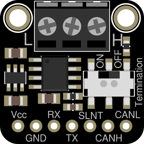
Pin Configuration and Descriptions
The CAN Pal features a standard pinout for easy integration with microcontrollers and development boards. Below is the pin configuration:
| Pin | Name | Description |
|---|---|---|
| 1 | VCC | Power supply input (3.3V or 5V, depending on the system voltage). |
| 2 | GND | Ground connection. |
| 3 | CS | Chip Select (SPI interface). |
| 4 | SCK | Serial Clock (SPI interface). |
| 5 | MOSI | Master Out Slave In (SPI interface). |
| 6 | MISO | Master In Slave Out (SPI interface). |
| 7 | INT | Interrupt pin, used to signal events to the microcontroller. |
| 8 | CAN_H | CAN bus high line, connects to the CAN network. |
| 9 | CAN_L | CAN bus low line, connects to the CAN network. |
Usage Instructions
The CAN Pal is straightforward to use in a circuit. Follow the steps below to integrate it into your project:
Step 1: Hardware Setup
- Connect the VCC and GND pins of the CAN Pal to the power supply of your system (3.3V or 5V).
- Connect the CS, SCK, MOSI, and MISO pins to the corresponding SPI pins on your microcontroller or development board.
- Connect the CAN_H and CAN_L pins to the CAN bus network.
- Optionally, connect the INT pin to a GPIO pin on your microcontroller to handle interrupts.
Step 2: Software Setup
If you are using an Arduino UNO, you can use the popular "MCP_CAN" library to communicate with the CAN Pal. Install the library via the Arduino IDE Library Manager.
Step 3: Example Code
Below is an example Arduino sketch to send a CAN message using the CAN Pal:
#include <SPI.h>
#include <mcp_can.h>

// Define the SPI Chip Select pin
#define CAN_CS 10

// Initialize the MCP_CAN object
MCP_CAN CAN(CAN_CS);

void setup() {
  Serial.begin(115200);

  // Initialize the CAN bus at 500 kbps
  if (CAN.begin(MCP_ANY, 500000, MCP_8MHZ) == CAN_OK) {
    Serial.println("CAN Pal initialized successfully!");
  } else {
    Serial.println("CAN Pal initialization failed!");
    while (1);
  }

  // Set the CAN bus to normal mode
  CAN.setMode(MCP_NORMAL);
  Serial.println("CAN bus set to normal mode.");
}

void loop() {
  // Define a sample CAN message
  unsigned char message[8] = {0x01, 0x02, 0x03, 0x04, 0x05, 0x06, 0x07, 0x08};

  // Send the CAN message with ID 0x100
  if (CAN.sendMsgBuf(0x100, 0, 8, message) == CAN_OK) {
    Serial.println("Message sent successfully!");
  } else {
    Serial.println("Error sending message.");
  }

  delay(1000); // Wait 1 second before sending the next message
}
Important Considerations and Best Practices
- Ensure proper termination of the CAN bus with 120-ohm resistors at both ends of the network.
- Use shielded twisted-pair cables for the CAN_H and CAN_L lines to minimize noise and interference.
- Verify that the CAN Pal's operating voltage matches your system's power supply.
- Avoid long cable runs to reduce signal degradation.
Troubleshooting and FAQs
Common Issues and Solutions
CAN Pal not initializing:
- Ensure the SPI connections (CS, SCK, MOSI, MISO) are correctly wired.
- Verify that the power supply voltage matches the CAN Pal's requirements.
- Check for loose or faulty connections.
No communication on the CAN bus:
- Confirm that the CAN_H and CAN_L lines are properly connected to the network.
- Ensure the CAN bus is terminated with 120-ohm resistors at both ends.
- Verify that all devices on the CAN bus are configured to use the same baud rate.
Interrupts not working:
- Check the connection between the INT pin and the microcontroller.
- Ensure the interrupt pin is correctly configured in your code.
FAQs
Q: Can the CAN Pal be used with 3.3V systems?
A: Yes, the CAN Pal supports both 3.3V and 5V systems. Ensure the VCC pin is connected to the appropriate voltage.
Q: What is the maximum data rate supported by the CAN Pal?
A: The CAN Pal supports data rates of up to 1 Mbps.
Q: Does the CAN Pal require external termination resistors?
A: Yes, the CAN bus must be terminated with 120-ohm resistors at both ends of the network for proper operation.
Q: Can I use the CAN Pal with microcontrollers other than Arduino?
A: Absolutely! The CAN Pal uses an SPI interface, making it compatible with a wide range of microcontrollers, including STM32, ESP32, and Raspberry Pi.
By following this documentation, you can effectively integrate the CAN Pal into your projects and take full advantage of its capabilities.