Cirkit Designer Logo
Cirkit Designer
Your all-in-one circuit design IDE
Home / 
Component Documentation

How to Use mini 2 in 1 3.7V 3.8V Li-Ion Li-Polymer Battery Charger & 4.2V to 3.3V 3V LDO Buck DC DC Converter Module UPS Diy: Examples, Pinouts, and Specs

Image of  mini 2 in 1 3.7V 3.8V Li-Ion Li-Polymer Battery Charger & 4.2V to 3.3V 3V LDO Buck DC DC Converter Module UPS Diy
Cirkit Designer LogoDesign with mini 2 in 1 3.7V 3.8V Li-Ion Li-Polymer Battery Charger & 4.2V to 3.3V 3V LDO Buck DC DC Converter Module UPS Diy in Cirkit Designer

Introduction

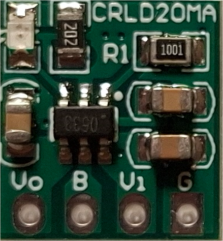
The CRLD20MA from Rsdz Store is a versatile and compact module designed to simplify power management in your electronic projects. This module combines a battery charger for 3.7V and 3.8V Li-Ion and Li-Polymer batteries with a low dropout (LDO) buck converter that steps down 4.2V to 3.3V or 3V. It is ideal for applications requiring an uninterruptible power supply (UPS) and various DIY projects.

Explore Projects Built with mini 2 in 1 3.7V 3.8V Li-Ion Li-Polymer Battery Charger & 4.2V to 3.3V 3V LDO Buck DC DC Converter Module UPS Diy

Use Cirkit Designer to design, explore, and prototype these projects online. Some projects support real-time simulation. Click "Open Project" to start designing instantly!
Battery-Powered 18650 Li-ion Charger with USB Output and Adjustable Voltage Regulator
Image of Breadboard: A project utilizing  mini 2 in 1 3.7V 3.8V Li-Ion Li-Polymer Battery Charger & 4.2V to 3.3V 3V LDO Buck DC DC Converter Module UPS Diy in a practical application
This circuit is a battery management and power supply system that uses three 3.7V batteries connected to a 3S 10A Li-ion 18650 Charger Protection Board Module for balanced charging and protection. The system includes a TP4056 Battery Charging Protection Module for additional charging safety, a Step Up Boost Power Converter to regulate and boost the voltage, and a USB regulator to provide a stable 5V output, controlled by a push switch.
Cirkit Designer LogoOpen Project in Cirkit Designer
Battery-Powered Lora G2 Node Station with 18650 Li-ion Batteries and Boost Converter
Image of Custom-Lora-G2-Node: A project utilizing  mini 2 in 1 3.7V 3.8V Li-Ion Li-Polymer Battery Charger & 4.2V to 3.3V 3V LDO Buck DC DC Converter Module UPS Diy in a practical application
This circuit is a portable power supply system that uses multiple 18650 Li-ion batteries to provide a stable 5V output through a boost converter. It includes a fast charging module with a USB-C input for recharging the batteries and a battery indicator for monitoring the battery status. The system powers a Lora G2 Node Station, making it suitable for wireless communication applications.
Cirkit Designer LogoOpen Project in Cirkit Designer
Battery-Powered Li-ion Charger with Digital Volt/Ammeter and Buzzer Alert
Image of multimeter: A project utilizing  mini 2 in 1 3.7V 3.8V Li-Ion Li-Polymer Battery Charger & 4.2V to 3.3V 3V LDO Buck DC DC Converter Module UPS Diy in a practical application
This circuit is a battery charging and monitoring system for a Li-ion battery using a TP4056 charger module. It includes a digital volt/ammeter to display the battery voltage and current, and features LEDs and a piezo buzzer for status indication. The circuit also incorporates switches for controlling the power and monitoring functions.
Cirkit Designer LogoOpen Project in Cirkit Designer
Battery-Powered UPS System with Waveshare UPS 3S and Solar Charger
Image of Copy of s: A project utilizing  mini 2 in 1 3.7V 3.8V Li-Ion Li-Polymer Battery Charger & 4.2V to 3.3V 3V LDO Buck DC DC Converter Module UPS Diy in a practical application
This circuit is a power management system that integrates a 12V power supply, a solar charger power bank, and multiple Li-ion batteries to provide a stable power output. The Waveshare UPS 3S manages the input from the power sources and batteries, ensuring continuous power delivery. The MRB045 module is used to interface the solar charger with the rest of the system.
Cirkit Designer LogoOpen Project in Cirkit Designer

Explore Projects Built with mini 2 in 1 3.7V 3.8V Li-Ion Li-Polymer Battery Charger & 4.2V to 3.3V 3V LDO Buck DC DC Converter Module UPS Diy

Use Cirkit Designer to design, explore, and prototype these projects online. Some projects support real-time simulation. Click "Open Project" to start designing instantly!
Image of Breadboard: A project utilizing  mini 2 in 1 3.7V 3.8V Li-Ion Li-Polymer Battery Charger & 4.2V to 3.3V 3V LDO Buck DC DC Converter Module UPS Diy in a practical application
Battery-Powered 18650 Li-ion Charger with USB Output and Adjustable Voltage Regulator
This circuit is a battery management and power supply system that uses three 3.7V batteries connected to a 3S 10A Li-ion 18650 Charger Protection Board Module for balanced charging and protection. The system includes a TP4056 Battery Charging Protection Module for additional charging safety, a Step Up Boost Power Converter to regulate and boost the voltage, and a USB regulator to provide a stable 5V output, controlled by a push switch.
Cirkit Designer LogoOpen Project in Cirkit Designer
Image of Custom-Lora-G2-Node: A project utilizing  mini 2 in 1 3.7V 3.8V Li-Ion Li-Polymer Battery Charger & 4.2V to 3.3V 3V LDO Buck DC DC Converter Module UPS Diy in a practical application
Battery-Powered Lora G2 Node Station with 18650 Li-ion Batteries and Boost Converter
This circuit is a portable power supply system that uses multiple 18650 Li-ion batteries to provide a stable 5V output through a boost converter. It includes a fast charging module with a USB-C input for recharging the batteries and a battery indicator for monitoring the battery status. The system powers a Lora G2 Node Station, making it suitable for wireless communication applications.
Cirkit Designer LogoOpen Project in Cirkit Designer
Image of multimeter: A project utilizing  mini 2 in 1 3.7V 3.8V Li-Ion Li-Polymer Battery Charger & 4.2V to 3.3V 3V LDO Buck DC DC Converter Module UPS Diy in a practical application
Battery-Powered Li-ion Charger with Digital Volt/Ammeter and Buzzer Alert
This circuit is a battery charging and monitoring system for a Li-ion battery using a TP4056 charger module. It includes a digital volt/ammeter to display the battery voltage and current, and features LEDs and a piezo buzzer for status indication. The circuit also incorporates switches for controlling the power and monitoring functions.
Cirkit Designer LogoOpen Project in Cirkit Designer
Image of Copy of s: A project utilizing  mini 2 in 1 3.7V 3.8V Li-Ion Li-Polymer Battery Charger & 4.2V to 3.3V 3V LDO Buck DC DC Converter Module UPS Diy in a practical application
Battery-Powered UPS System with Waveshare UPS 3S and Solar Charger
This circuit is a power management system that integrates a 12V power supply, a solar charger power bank, and multiple Li-ion batteries to provide a stable power output. The Waveshare UPS 3S manages the input from the power sources and batteries, ensuring continuous power delivery. The MRB045 module is used to interface the solar charger with the rest of the system.
Cirkit Designer LogoOpen Project in Cirkit Designer

Common Applications

  • Portable electronic devices
  • Battery-powered projects
  • Uninterruptible power supplies (UPS)
  • DIY electronics and prototyping
  • Wearable technology

Technical Specifications

Key Technical Details

Parameter Value
Input Voltage 4.2V
Output Voltage 3.3V or 3V (selectable)
Charging Voltage 3.7V / 3.8V
Charging Current 500mA
Output Current 500mA
Efficiency Up to 95%
Dimensions 22mm x 17mm x 4mm
Operating Temperature -40°C to 85°C

Pin Configuration and Descriptions

Pin No. Pin Name Description
1 VIN Input Voltage (4.2V)
2 GND Ground
3 BAT+ Battery Positive Terminal (3.7V / 3.8V)
4 BAT- Battery Negative Terminal
5 VOUT Output Voltage (3.3V or 3V)
6 SEL Voltage Selection Pin (High for 3.3V, Low for 3V)

Usage Instructions

How to Use the Component in a Circuit

  1. Power Input: Connect the input voltage (4.2V) to the VIN pin and the ground to the GND pin.
  2. Battery Connection: Connect the positive terminal of the battery to the BAT+ pin and the negative terminal to the BAT- pin.
  3. Output Voltage: Connect your load to the VOUT pin and ground to the GND pin.
  4. Voltage Selection: Use the SEL pin to select the output voltage. Connect it to a high logic level (e.g., VIN) for 3.3V output or to a low logic level (e.g., GND) for 3V output.

Important Considerations and Best Practices

  • Ensure the input voltage does not exceed 4.2V to prevent damage to the module.
  • Use appropriate heat dissipation methods if the module operates at high currents for extended periods.
  • Verify the battery specifications to ensure compatibility with the charging voltage and current.
  • Double-check all connections before powering up the module to avoid short circuits or incorrect wiring.

Troubleshooting and FAQs

Common Issues and Solutions

  1. Module Not Powering Up

    • Solution: Check the input voltage to ensure it is 4.2V. Verify all connections, especially the VIN and GND pins.
  2. Battery Not Charging

    • Solution: Ensure the battery is properly connected to the BAT+ and BAT- pins. Verify the battery specifications match the module's charging voltage and current.
  3. Incorrect Output Voltage

    • Solution: Check the SEL pin connection. Ensure it is correctly set to high or low for the desired output voltage (3.3V or 3V).
  4. Overheating

    • Solution: Ensure proper ventilation and consider adding a heatsink if the module operates at high currents for long durations.

FAQs

Q1: Can I use this module with an Arduino UNO?

  • A1: Yes, you can use this module to power an Arduino UNO. Connect the VOUT pin to the 3.3V or 3V input of the Arduino, depending on your selection.

Q2: What type of batteries are compatible with this module?

  • A2: This module is compatible with 3.7V and 3.8V Li-Ion and Li-Polymer batteries.

Q3: How do I select the output voltage?

  • A3: Use the SEL pin to select the output voltage. Connect it to a high logic level (e.g., VIN) for 3.3V output or to a low logic level (e.g., GND) for 3V output.

Example Code for Arduino UNO

// Example code to monitor battery voltage using Arduino UNO
const int batteryPin = A0; // Analog pin connected to VOUT
float batteryVoltage = 0.0;

void setup() {
  Serial.begin(9600); // Initialize serial communication
}

void loop() {
  int sensorValue = analogRead(batteryPin); // Read the analog input
  batteryVoltage = sensorValue * (5.0 / 1023.0); // Convert to voltage
  Serial.print("Battery Voltage: ");
  Serial.println(batteryVoltage); // Print the battery voltage
  delay(1000); // Wait for 1 second before next reading
}

This code reads the battery voltage from the VOUT pin and prints it to the serial monitor. Ensure the VOUT pin is connected to an analog input pin on the Arduino UNO.

By following this documentation, you can effectively integrate the CRLD20MA module into your projects, ensuring reliable power management and efficient battery charging.