How to Use 5V UPS: Examples, Pinouts, and Specs
Introduction
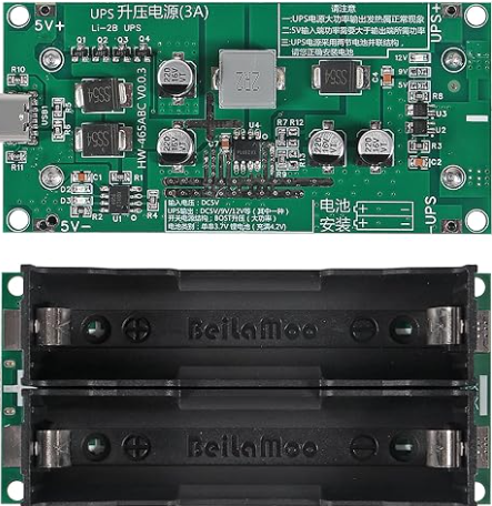
A 5V Uninterruptible Power Supply (UPS) is a compact power management device designed to provide a stable 5V output to electronic devices during power outages or fluctuations. It ensures uninterrupted operation by seamlessly switching to a rechargeable battery when the primary power source is unavailable. This makes it an essential component for critical systems, IoT devices, Raspberry Pi boards, and other low-power electronics that require reliable power delivery.
Explore Projects Built with 5V UPS


Explore Projects Built with 5V UPS
Common Applications and Use Cases
- Backup power for Raspberry Pi, Arduino, and other microcontroller-based systems.
- IoT devices deployed in remote or unstable power environments.
- Network equipment such as routers and modems.
- Portable electronics requiring stable 5V power.
- Data logging systems to prevent data loss during power interruptions.
Technical Specifications
The following table outlines the key technical details of the 5V UPS:
| Parameter | Value |
|---|---|
| Input Voltage Range | 5V DC ± 5% |
| Output Voltage | 5V DC ± 2% |
| Maximum Output Current | 2A |
| Battery Type | Lithium-ion or Lithium-polymer |
| Battery Capacity | Typically 1000mAh to 5000mAh |
| Charging Current | 1A (typical) |
| Switching Time | < 10ms |
| Operating Temperature | -10°C to 60°C |
| Dimensions | Varies by model (e.g., 50x30x10mm) |
Pin Configuration and Descriptions
The 5V UPS typically includes the following pins or connectors:
| Pin/Connector | Description |
|---|---|
| VIN | Input voltage pin for connecting a 5V DC power source. |
| VOUT | Output voltage pin providing a stable 5V DC supply to the load. |
| GND | Ground pin shared by the input, output, and battery. |
| BAT+ | Positive terminal for connecting the rechargeable battery (if external). |
| BAT- | Negative terminal for connecting the rechargeable battery (if external). |
| CHG_IND | Charging indicator pin (optional) - active when the battery is charging. |
| PWR_GOOD | Power status indicator pin (optional) - signals when the output is stable. |
Usage Instructions
How to Use the 5V UPS in a Circuit
Connect the Input Power Source:
Attach a 5V DC power source to theVINandGNDpins. Ensure the input voltage is within the specified range to avoid damage.Connect the Load:
Connect the device or circuit requiring backup power to theVOUTandGNDpins. Verify that the load does not exceed the maximum output current (2A).Attach the Battery:
If the UPS requires an external battery, connect the positive and negative terminals of the battery to theBAT+andBAT-pins, respectively. Use a compatible lithium-ion or lithium-polymer battery.Monitor Indicators (Optional):
- Use the
CHG_INDpin to monitor the charging status of the battery. - Use the
PWR_GOODpin to check if the output voltage is stable.
- Use the
Test the UPS Functionality:
Disconnect the input power source to simulate a power outage. Verify that the UPS seamlessly switches to battery power and maintains a stable 5V output.
Important Considerations and Best Practices
- Battery Selection: Use a battery with sufficient capacity to meet the runtime requirements of your application. Ensure the battery voltage matches the UPS specifications.
- Heat Management: Avoid placing the UPS in enclosed spaces without ventilation, as heat may build up during operation or charging.
- Load Limitations: Do not exceed the maximum output current (2A) to prevent damage to the UPS or connected devices.
- Regular Maintenance: Periodically check the battery health and replace it if the capacity significantly degrades.
Example: Using a 5V UPS with an Arduino UNO
The following example demonstrates how to connect a 5V UPS to an Arduino UNO for uninterrupted operation:
Circuit Connections
- Connect the
VOUTpin of the UPS to the 5V pin of the Arduino UNO. - Connect the
GNDpin of the UPS to the GND pin of the Arduino UNO. - Optionally, monitor the
PWR_GOODpin to detect power stability.
Sample Code
// Example code to monitor the PWR_GOOD pin of a 5V UPS
const int powerGoodPin = 2; // Connect PWR_GOOD pin to Arduino digital pin 2
const int ledPin = 13;      // Built-in LED on Arduino UNO

void setup() {
  pinMode(powerGoodPin, INPUT); // Set PWR_GOOD pin as input
  pinMode(ledPin, OUTPUT);      // Set LED pin as output
  digitalWrite(ledPin, LOW);    // Turn off LED initially
  Serial.begin(9600);           // Initialize serial communication
}

void loop() {
  int powerStatus = digitalRead(powerGoodPin); // Read PWR_GOOD pin status

  if (powerStatus == HIGH) {
    // Power is stable, turn off LED
    digitalWrite(ledPin, LOW);
    Serial.println("Power is stable.");
  } else {
    // Power is unstable, turn on LED
    digitalWrite(ledPin, HIGH);
    Serial.println("Power is unstable! Running on battery.");
  }

  delay(1000); // Wait for 1 second before checking again
}
Troubleshooting and FAQs
Common Issues and Solutions
UPS Not Switching to Battery Power
- Cause: Battery is not connected or is discharged.
- Solution: Verify the battery connections and ensure the battery is charged.
Output Voltage Drops Below 5V
- Cause: Load exceeds the maximum output current or battery is low.
- Solution: Reduce the load or replace/charge the battery.
Battery Overheating During Charging
- Cause: Faulty battery or inadequate ventilation.
- Solution: Replace the battery and ensure proper ventilation.
CHG_IND or PWR_GOOD Pins Not Responding
- Cause: Incorrect wiring or damaged pins.
- Solution: Check the connections and test the pins with a multimeter.
FAQs
Q1: Can I use the 5V UPS with a 3.3V device?
A1: No, the 5V UPS is designed to provide a stable 5V output. Use a voltage regulator or level shifter for 3.3V devices.
Q2: How long will the UPS run on battery power?
A2: The runtime depends on the battery capacity and the power consumption of the connected load. For example, a 2000mAh battery powering a 500mA load will last approximately 4 hours.
Q3: Can I charge the battery while the UPS is powering a device?
A3: Yes, most 5V UPS modules support simultaneous charging and powering of the load.
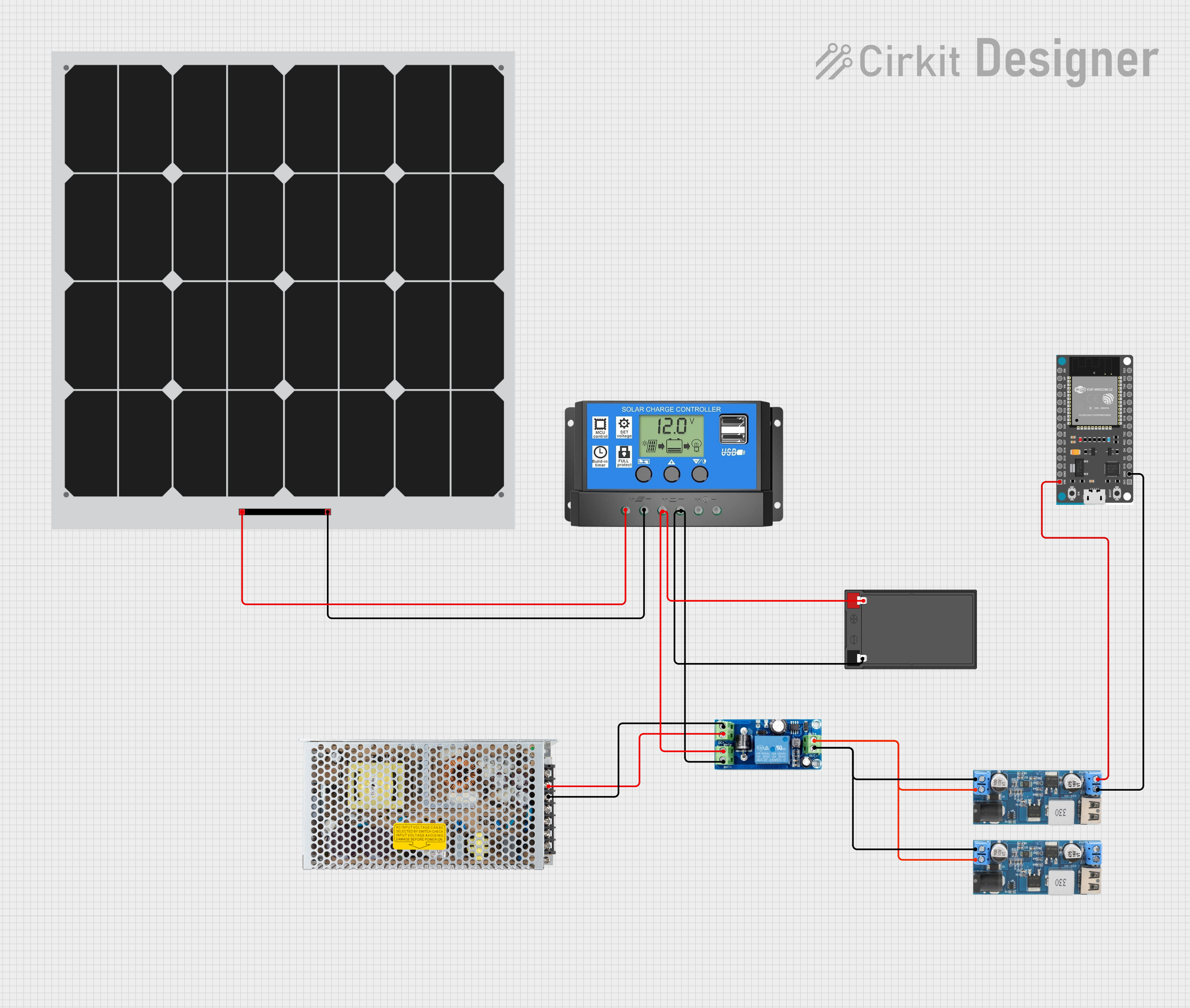
Q4: Is the UPS compatible with solar panels?
A4: Yes, as long as the solar panel provides a stable 5V output within the input voltage range of the UPS.