How to Use STM32F103: Examples, Pinouts, and Specs
Introduction
The STM32F103 is a 32-bit microcontroller developed by STMicroelectronics, based on the ARM Cortex-M3 core. It is widely recognized for its low power consumption, high performance, and extensive peripheral set. This microcontroller is part of the STM32 family and is designed to meet the needs of a variety of embedded applications, including industrial automation, consumer electronics, IoT devices, and motor control systems.
Explore Projects Built with STM32F103


Explore Projects Built with STM32F103
Common Applications and Use Cases
- Industrial control systems
- IoT devices and smart home applications
- Motor control and robotics
- Medical devices
- Consumer electronics
- Data acquisition systems
Technical Specifications
Key Technical Details
- Core: ARM Cortex-M3, 32-bit RISC
- Operating Frequency: Up to 72 MHz
- Flash Memory: 16 KB to 1 MB (depending on the variant)
- SRAM: 6 KB to 96 KB
- Operating Voltage: 2.0V to 3.6V
- I/O Pins: Up to 112 GPIOs (depending on the package)
- Communication Interfaces:
- Up to 3 USARTs
- Up to 2 I2C interfaces
- Up to 2 SPI interfaces
- CAN 2.0B
- USB 2.0 Full-Speed
- Timers: 7 timers (including advanced control timers for PWM)
- ADC: 12-bit ADC with up to 16 channels
- Power Modes: Sleep, Stop, and Standby for low power consumption
- Package Options: LQFP48, LQFP64, LQFP100, etc.
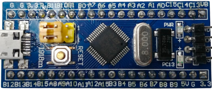
Pin Configuration and Descriptions
Below is an example of the pin configuration for the STM32F103 in the LQFP48 package:
| Pin Number | Pin Name | Function | Description |
|---|---|---|---|
| 1 | VDD | Power Supply | Positive power supply (2.0V to 3.6V) |
| 2 | VDDA | Analog Power Supply | Power supply for ADC and DAC |
| 3 | PA0 | GPIO/ADC_IN0 | General-purpose I/O or ADC input channel |
| 4 | PA1 | GPIO/ADC_IN1 | General-purpose I/O or ADC input channel |
| 5 | PA2 | GPIO/USART2_TX | General-purpose I/O or USART2 transmit |
| 6 | PA3 | GPIO/USART2_RX | General-purpose I/O or USART2 receive |
| 7 | PA4 | GPIO/SPI1_NSS/ADC_IN4 | General-purpose I/O or SPI1 chip select |
| 8 | PA5 | GPIO/SPI1_SCK/ADC_IN5 | General-purpose I/O or SPI1 clock |
| ... | ... | ... | ... |
For a complete pinout, refer to the STM32F103 datasheet.
Usage Instructions
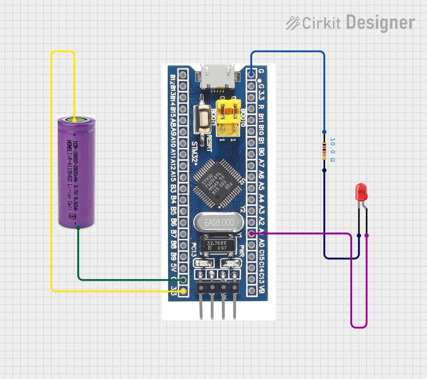
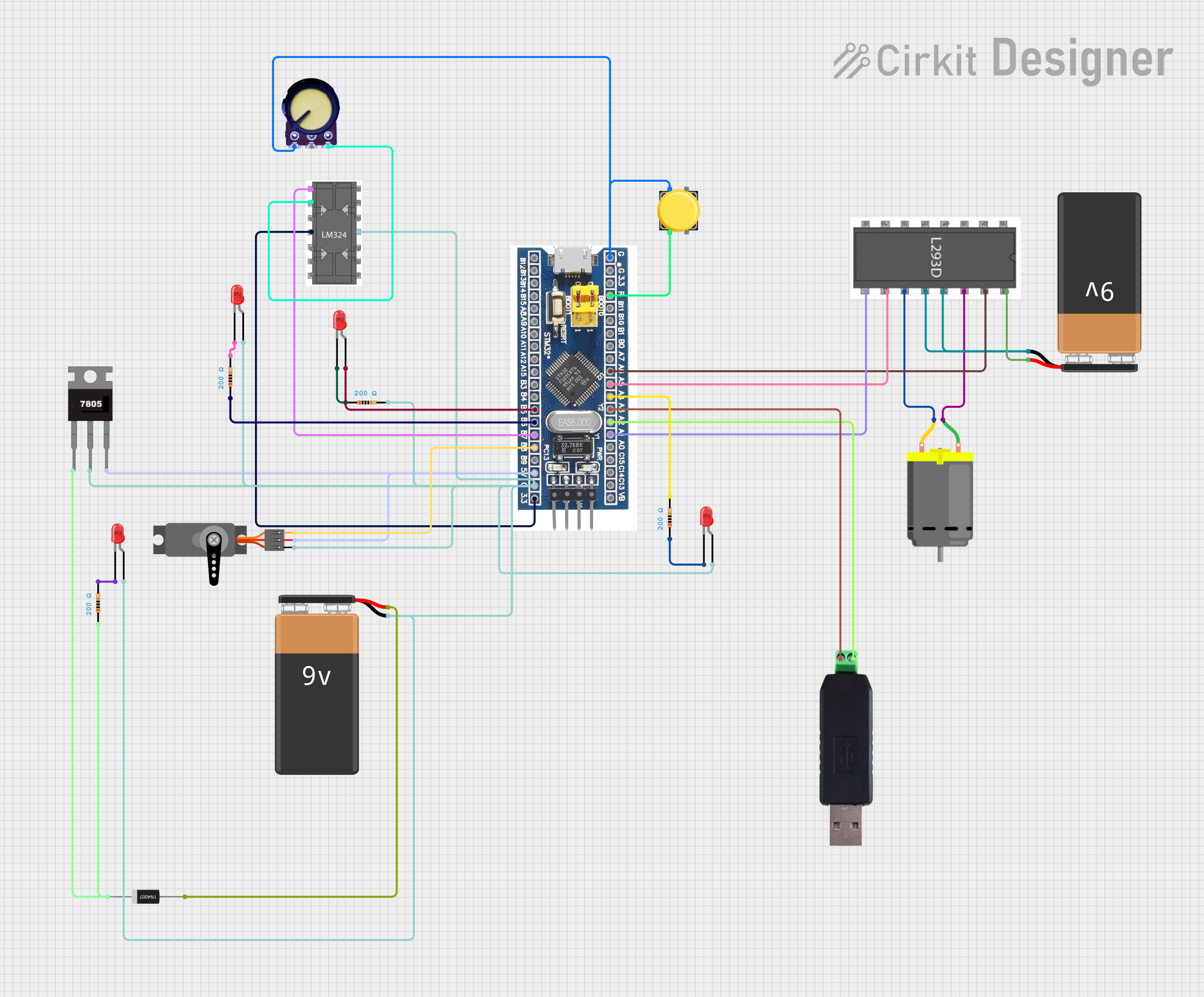
How to Use the STM32F103 in a Circuit
- Power Supply: Connect the VDD and VDDA pins to a stable power source (2.0V to 3.6V). Use decoupling capacitors (e.g., 0.1 µF) close to the power pins to reduce noise.
- Clock Configuration: The STM32F103 can use an external crystal oscillator or its internal RC oscillator. For precise timing, connect an external crystal (e.g., 8 MHz) to the OSC_IN and OSC_OUT pins.
- Reset Pin: Connect the NRST pin to a pull-up resistor (e.g., 10 kΩ) to ensure proper reset functionality.
- Programming: Use the SWD (Serial Wire Debug) interface for programming and debugging. Connect the SWDIO and SWCLK pins to a compatible programmer (e.g., ST-Link).
- Peripherals: Configure the GPIO pins and peripherals (e.g., USART, SPI, I2C) in the firmware using STM32CubeMX or direct register programming.
Important Considerations and Best Practices
- Power Management: Use the low-power modes (Sleep, Stop, Standby) to reduce power consumption in battery-powered applications.
- Decoupling Capacitors: Place decoupling capacitors close to the power pins to minimize noise and ensure stable operation.
- Boot Mode Selection: Use the BOOT0 and BOOT1 pins to select the boot mode (e.g., boot from Flash, SRAM, or system memory).
- ESD Protection: Add ESD protection diodes on GPIO pins exposed to external connections.
Example: Interfacing STM32F103 with Arduino UNO
The STM32F103 can communicate with an Arduino UNO via UART. Below is an example of Arduino code to send data to the STM32F103:
Arduino Code
void setup() {
  Serial.begin(9600); // Initialize UART communication at 9600 baud
}

void loop() {
  Serial.println("Hello from Arduino!"); // Send data to STM32F103
  delay(1000); // Wait for 1 second
}
STM32F103 Code (Using HAL Library)
#include "stm32f1xx_hal.h"

UART_HandleTypeDef huart1; // UART handle for USART1

void SystemClock_Config(void);
void MX_USART1_UART_Init(void);

int main(void) {
  HAL_Init(); // Initialize the HAL library
  SystemClock_Config(); // Configure the system clock
  MX_USART1_UART_Init(); // Initialize USART1

  char rxData[50]; // Buffer to store received data

  while (1) {
    if (HAL_UART_Receive(&huart1, (uint8_t *)rxData, sizeof(rxData), 1000) == HAL_OK) {
      HAL_UART_Transmit(&huart1, (uint8_t *)rxData, strlen(rxData), 1000);
      // Echo received data back to the sender
    }
  }
}

void MX_USART1_UART_Init(void) {
  huart1.Instance = USART1;
  huart1.Init.BaudRate = 9600;
  huart1.Init.WordLength = UART_WORDLENGTH_8B;
  huart1.Init.StopBits = UART_STOPBITS_1;
  huart1.Init.Parity = UART_PARITY_NONE;
  huart1.Init.Mode = UART_MODE_TX_RX;
  huart1.Init.HwFlowCtl = UART_HWCONTROL_NONE;
  huart1.Init.OverSampling = UART_OVERSAMPLING_16;
  HAL_UART_Init(&huart1);
}
Troubleshooting and FAQs
Common Issues and Solutions
Microcontroller Not Responding:
- Ensure the power supply is stable and within the operating range (2.0V to 3.6V).
- Check the reset pin (NRST) and ensure it is not held low.
Programming Failure:
- Verify the SWD connections (SWDIO, SWCLK) and ensure the programmer is properly connected.
- Check the BOOT0 pin configuration. For Flash programming, BOOT0 should be set to 0.
Peripheral Not Working:
- Double-check the GPIO pin configuration in the firmware.
- Ensure the clock for the peripheral is enabled in the RCC (Reset and Clock Control) register.
High Power Consumption:
- Use low-power modes (Sleep, Stop, Standby) when the microcontroller is idle.
- Disable unused peripherals to reduce power consumption.
FAQs
Q: Can the STM32F103 be programmed using the Arduino IDE?
A: Yes, the STM32F103 can be programmed using the Arduino IDE with the STM32duino core installed.Q: What is the maximum clock speed of the STM32F103?
A: The STM32F103 can operate at a maximum clock speed of 72 MHz.Q: How do I select the boot mode?
A: Use the BOOT0 and BOOT1 pins to select the boot mode. Refer to the datasheet for the boot mode table.Q: Can I use the STM32F103 for USB communication?
A: Yes, the STM32F103 includes a USB 2.0 Full-Speed interface for USB communication.