How to Use ESP32-WROOM-32: Examples, Pinouts, and Specs
Introduction
The ESP32-WROOM-32 is a powerful Wi-Fi and Bluetooth microcontroller module designed for IoT applications and embedded systems. It features dual-core processing, making it suitable for tasks requiring high performance and multitasking capabilities. With integrated Wi-Fi and Bluetooth (Classic and BLE), the ESP32-WROOM-32 is ideal for smart home devices, wearables, industrial automation, and other connected applications.
Explore Projects Built with ESP32-WROOM-32


Explore Projects Built with ESP32-WROOM-32
Common Applications
- Smart home devices (e.g., smart lights, thermostats)
- IoT sensors and gateways
- Wearable devices
- Industrial automation and control systems
- Robotics and drones
- Wireless data logging and monitoring
Technical Specifications
Key Technical Details
- Processor: Dual-core Xtensa® 32-bit LX6 microprocessor
- Clock Speed: Up to 240 MHz
- Flash Memory: 4 MB (external SPI flash)
- RAM: 520 KB SRAM
- Wi-Fi: 802.11 b/g/n (2.4 GHz)
- Bluetooth: v4.2 BR/EDR and BLE
- Operating Voltage: 3.0V to 3.6V
- GPIO Pins: 34 (multipurpose, including ADC, DAC, PWM, I2C, SPI, UART)
- ADC Resolution: 12-bit
- DAC Resolution: 8-bit
- Power Consumption: Ultra-low power consumption in deep sleep mode (~10 µA)
- Operating Temperature: -40°C to 85°C
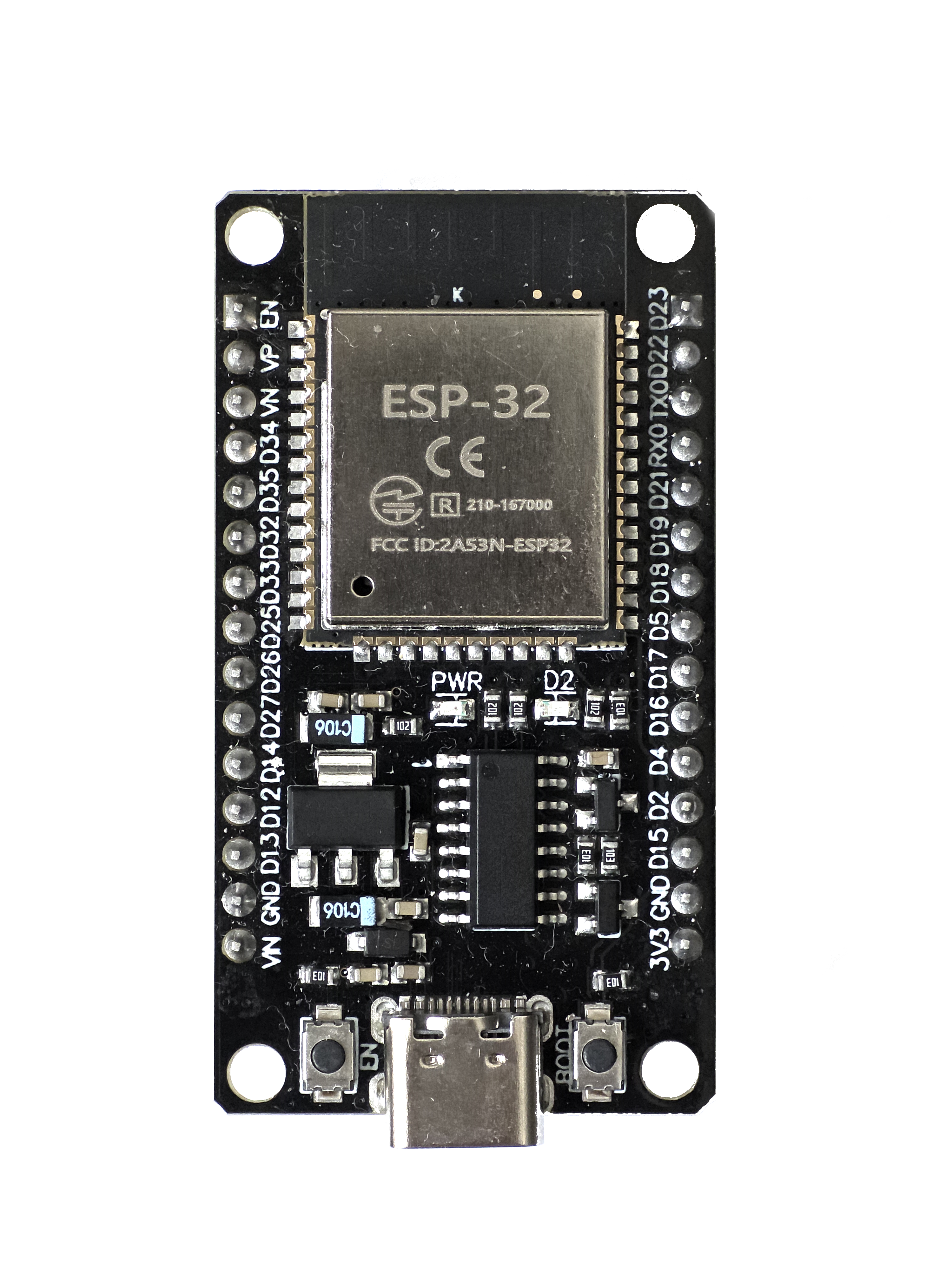
Pin Configuration and Descriptions
The ESP32-WROOM-32 module has 38 pins. Below is a table of the most commonly used pins and their functions:
| Pin | Name | Function |
|---|---|---|
| 1 | EN | Enable pin. Pull high to enable the module. |
| 2 | GPIO0 | General-purpose I/O, boot mode selection during startup. |
| 3 | GPIO2 | General-purpose I/O, often used for bootstrapping. |
| 4 | GPIO4 | General-purpose I/O, supports PWM, ADC, etc. |
| 5 | GPIO5 | General-purpose I/O, supports PWM, ADC, etc. |
| 6-11 | Flash Pins | Internal SPI flash memory connections (not for user access). |
| 12 | GPIO12 | General-purpose I/O, supports ADC, PWM, etc. |
| 13 | GPIO13 | General-purpose I/O, supports ADC, PWM, etc. |
| 14 | GPIO14 | General-purpose I/O, supports ADC, PWM, etc. |
| 15 | GPIO15 | General-purpose I/O, supports ADC, PWM, etc. |
| 16 | GPIO16 | General-purpose I/O, supports ADC, PWM, etc. |
| 17 | GPIO17 | General-purpose I/O, supports ADC, PWM, etc. |
| 18 | GPIO18 | SPI clock pin (SCK) for hardware SPI. |
| 19 | GPIO19 | SPI master-out/slave-in (MOSI) for hardware SPI. |
| 21 | GPIO21 | I2C data (SDA) pin. |
| 22 | GPIO22 | I2C clock (SCL) pin. |
| 23 | GPIO23 | SPI master-in/slave-out (MISO) for hardware SPI. |
| 25 | GPIO25 | DAC output channel 1. |
| 26 | GPIO26 | DAC output channel 2. |
| 27 | GPIO27 | General-purpose I/O, supports ADC, PWM, etc. |
| 32 | GPIO32 | ADC input channel 4. |
| 33 | GPIO33 | ADC input channel 5. |
| 34 | GPIO34 | ADC input channel 6 (input only). |
| 35 | GPIO35 | ADC input channel 7 (input only). |
| 36 | GPIO36 (VP) | ADC input channel 0 (input only). |
| 39 | GPIO39 (VN) | ADC input channel 3 (input only). |
Note: Some GPIO pins have specific bootstrapping functions and should not be pulled high or low during startup.
Usage Instructions
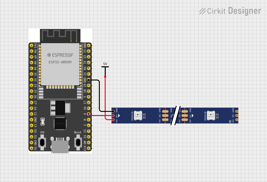
How to Use the ESP32-WROOM-32 in a Circuit
- Power Supply: Provide a stable 3.3V power supply to the module. Avoid exceeding 3.6V to prevent damage.
- Boot Mode: Connect GPIO0 to GND during startup to enter flashing mode. For normal operation, leave GPIO0 unconnected or pull it high.
- Programming: Use a USB-to-serial adapter (e.g., FTDI or CP2102) to program the ESP32-WROOM-32. Connect the adapter's TX to RX0 (GPIO3) and RX to TX0 (GPIO1).
- Peripherals: Connect sensors, actuators, or other peripherals to the GPIO pins. Use appropriate pull-up or pull-down resistors as needed.
- Antenna: Ensure the onboard antenna has a clear path for optimal Wi-Fi and Bluetooth performance.
Important Considerations and Best Practices
- Voltage Levels: The ESP32-WROOM-32 operates at 3.3V logic levels. Avoid connecting 5V signals directly to its GPIO pins.
- Deep Sleep Mode: Use deep sleep mode to minimize power consumption in battery-powered applications.
- Pin Multiplexing: Many GPIO pins have multiple functions (e.g., ADC, PWM, I2C). Configure the pins appropriately in your code.
- Heat Dissipation: Ensure proper ventilation or heat sinking if the module operates at high loads for extended periods.
Example Code for Arduino UNO
Below is an example of how to blink an LED connected to GPIO2 using the Arduino IDE:
// Include the ESP32 library
#include <Arduino.h>

// Define the GPIO pin for the LED
#define LED_PIN 2

void setup() {
  // Set the LED pin as an output
  pinMode(LED_PIN, OUTPUT);
}

void loop() {
  // Turn the LED on
  digitalWrite(LED_PIN, HIGH);
  delay(1000); // Wait for 1 second

  // Turn the LED off
  digitalWrite(LED_PIN, LOW);
  delay(1000); // Wait for 1 second
}
Note: Install the ESP32 board package in the Arduino IDE before uploading the code. Go to
File > Preferences, add the ESP32 board URL, and install the package via the Board Manager.
Troubleshooting and FAQs
Common Issues and Solutions
Module Not Detected by PC:
- Ensure the USB-to-serial adapter drivers are installed.
- Check the connections between the adapter and the ESP32 module.
- Verify that GPIO0 is connected to GND during flashing.
Wi-Fi Connection Fails:
- Double-check the SSID and password in your code.
- Ensure the Wi-Fi network is within range and not using unsupported security protocols.
GPIO Pin Not Working:
- Verify that the pin is not being used for another function (e.g., bootstrapping).
- Check for short circuits or incorrect wiring.
High Power Consumption:
- Use deep sleep mode to reduce power usage.
- Disconnect unused peripherals to minimize current draw.
FAQs
Q: Can the ESP32-WROOM-32 operate on 5V?
A: No, the module operates at 3.3V. Use a voltage regulator or level shifter for 5V systems.Q: How do I reset the module?
A: Pull the EN pin low momentarily to reset the module.Q: Can I use the ESP32-WROOM-32 with a breadboard?
A: Yes, but ensure the module's pins are properly aligned and connected to avoid shorts.Q: What is the maximum Wi-Fi range?
A: The range depends on the environment but typically extends up to 100 meters in open spaces.
By following this documentation, you can effectively integrate the ESP32-WROOM-32 into your projects and troubleshoot common issues.