How to Use Connector 2 In 12 Out: Examples, Pinouts, and Specs
Introduction
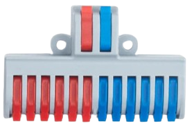
The Connector 2 In 12 Out is a versatile electronic component designed to distribute two input signals across twelve output channels. This component is widely used in audio and data applications where efficient signal routing is required. It ensures minimal signal loss and provides a reliable way to manage multiple output connections from a limited number of input sources.
Explore Projects Built with Connector 2 In 12 Out
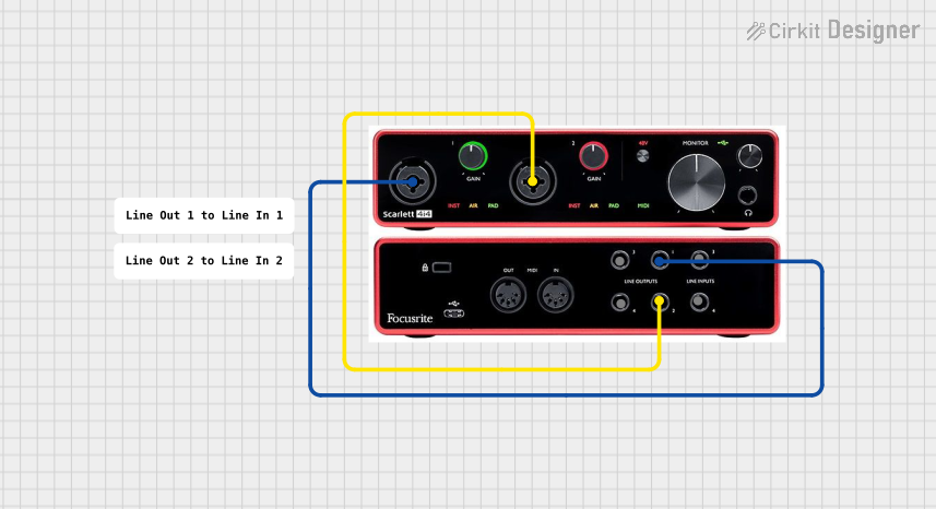


Explore Projects Built with Connector 2 In 12 Out
Common Applications and Use Cases
- Audio Systems: Distributing stereo audio signals to multiple speakers or amplifiers.
- Data Distribution: Splitting data signals for parallel processing or monitoring.
- Signal Testing: Routing signals to multiple test points in electronic circuits.
- Broadcast Systems: Distributing audio or video signals to multiple endpoints.
Technical Specifications
The following table outlines the key technical details of the Connector 2 In 12 Out:
| Parameter | Value |
|---|---|
| Input Channels | 2 |
| Output Channels | 12 |
| Signal Type | Analog or Digital |
| Maximum Voltage | 24V DC |
| Maximum Current | 1A per channel |
| Signal Loss | < 0.5% |
| Operating Temperature | -20°C to 70°C |
| Connector Type | Screw Terminals or Pin Headers |
| Dimensions | 50mm x 30mm x 15mm |
Pin Configuration and Descriptions
The Connector 2 In 12 Out has a straightforward pin layout. Below is the pin configuration:
| Pin Number | Label | Description |
|---|---|---|
| 1 | IN1 | Input signal 1 |
| 2 | IN2 | Input signal 2 |
| 3-14 | OUT1-OUT12 | Output channels corresponding to IN1 and IN2 |
| 15 | GND | Ground connection for signal reference |
Usage Instructions
How to Use the Component in a Circuit
- Connect the Inputs:
- Attach the input signals to the
IN1andIN2terminals. Ensure the input voltage and current do not exceed the specified limits.
- Attach the input signals to the
- Connect the Outputs:
- Connect the desired output devices (e.g., speakers, sensors, or other circuits) to the
OUT1throughOUT12terminals.
- Connect the desired output devices (e.g., speakers, sensors, or other circuits) to the
- Ground Connection:
- Connect the
GNDterminal to the ground of your circuit to ensure proper signal reference and stability.
- Connect the
- Power Considerations:
- If the output devices require power, ensure the power source is compatible with the component's maximum voltage and current ratings.
Important Considerations and Best Practices
- Signal Integrity: Use shielded cables for input and output connections to minimize noise and interference.
- Load Balancing: Avoid overloading any single output channel. Distribute the load evenly across the outputs.
- Temperature Management: Ensure the component operates within the specified temperature range to prevent damage.
- Testing: Before connecting sensitive devices, test the component with a multimeter to verify proper signal distribution.
Example: Using with an Arduino UNO
The Connector 2 In 12 Out can be used to distribute signals from an Arduino UNO to multiple devices. Below is an example of how to send a PWM signal from the Arduino to multiple outputs:
// Example: Distributing a PWM signal from Arduino to multiple outputs
// This code generates a PWM signal on pin 9 and distributes it via the connector.

const int pwmPin = 9; // Arduino pin connected to IN1 of the connector

void setup() {
  pinMode(pwmPin, OUTPUT); // Set pin 9 as an output
}

void loop() {
  analogWrite(pwmPin, 128); // Generate a 50% duty cycle PWM signal
  delay(1000); // Wait for 1 second
  analogWrite(pwmPin, 255); // Generate a 100% duty cycle PWM signal
  delay(1000); // Wait for 1 second
}
Note: Ensure the total current drawn by all connected devices does not exceed the Arduino's pin current limit (40mA per pin).
Troubleshooting and FAQs
Common Issues and Solutions
No Signal at Outputs:
- Cause: Input signal not connected or insufficient voltage.
- Solution: Verify the input connections and ensure the input signal meets the required specifications.
Signal Loss or Noise:
- Cause: Poor-quality cables or interference.
- Solution: Use shielded cables and keep the component away from high-frequency noise sources.
Overheating:
- Cause: Exceeding the maximum current or operating temperature.
- Solution: Reduce the load on the outputs and ensure proper ventilation.
Uneven Signal Distribution:
- Cause: Unequal load on output channels.
- Solution: Balance the load across all output channels.
FAQs
Q: Can this component handle both analog and digital signals?
A: Yes, the connector is compatible with both analog and digital signals, provided they are within the specified voltage and current limits.Q: Can I use this component for AC signals?
A: No, this component is designed for DC signals only.Q: What happens if I connect fewer than 12 outputs?
A: The unused output channels will remain inactive and will not affect the performance of the active channels.Q: Can I cascade multiple connectors for more outputs?
A: Yes, you can cascade connectors, but ensure the input signal strength is sufficient to drive all outputs.
This concludes the documentation for the Connector 2 In 12 Out. For further assistance, refer to the manufacturer's datasheet or contact technical support.