
How to Use PCA9548 8CH I2C MULTIPLEXER: Examples, Pinouts, and Specs
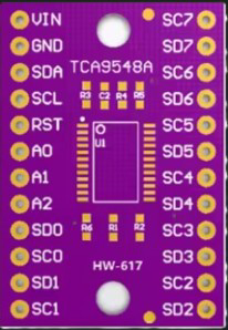
 Design with PCA9548 8CH I2C MULTIPLEXER in Cirkit Designer
Introduction
The PCA9548 is an 8-channel I2C multiplexer designed to expand the number of I2C devices that can be connected to a single I2C bus. It allows the user to select one of eight downstream I2C channels to communicate with a specific device, while isolating the other channels. This functionality is particularly useful in applications where multiple devices with the same I2C address need to coexist on the same bus.
Explore Projects Built with PCA9548 8CH I2C MULTIPLEXER
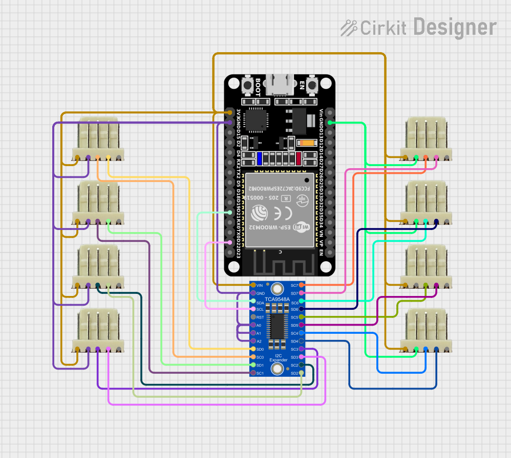 Open Project in Cirkit Designer
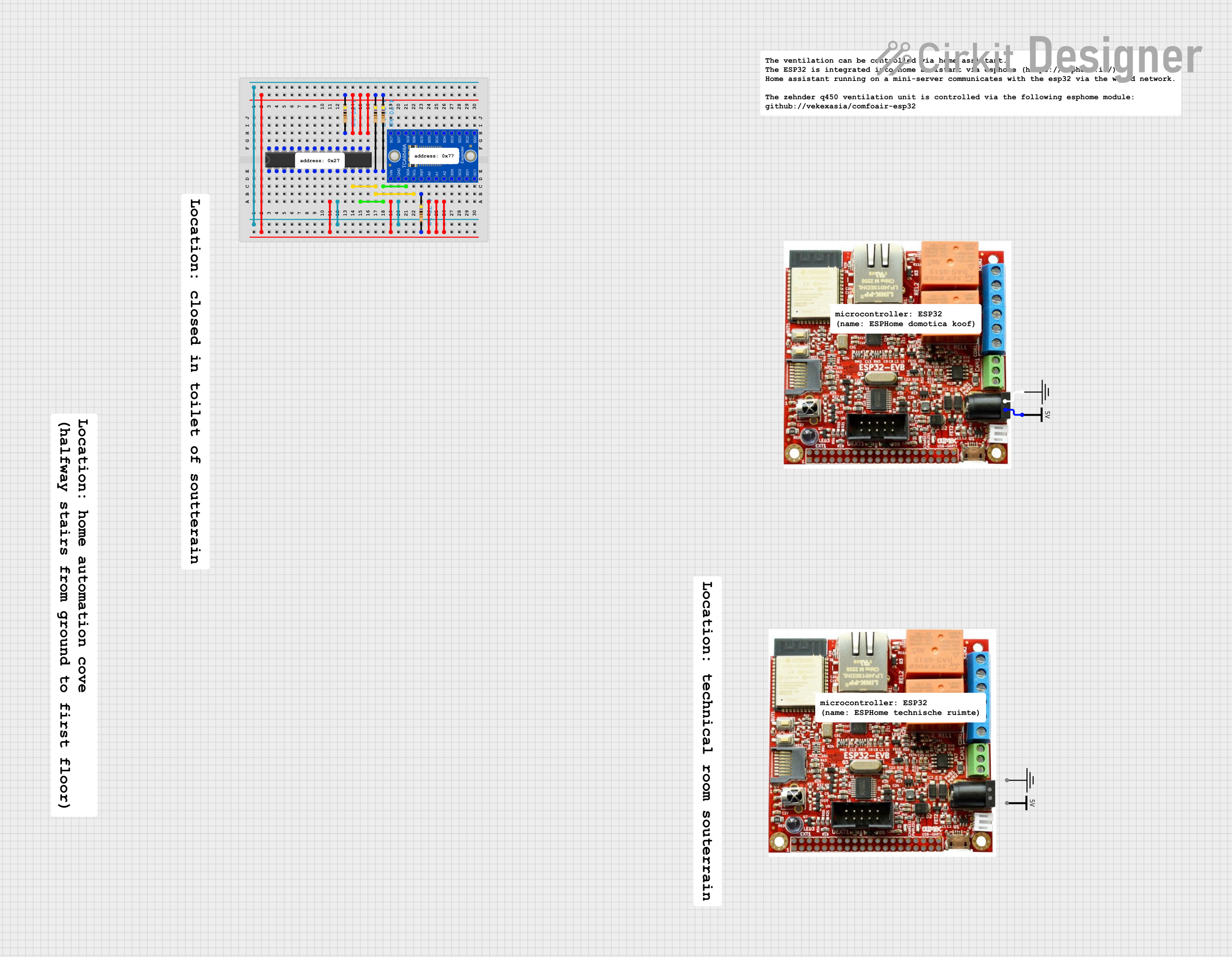 Open Project in Cirkit Designer
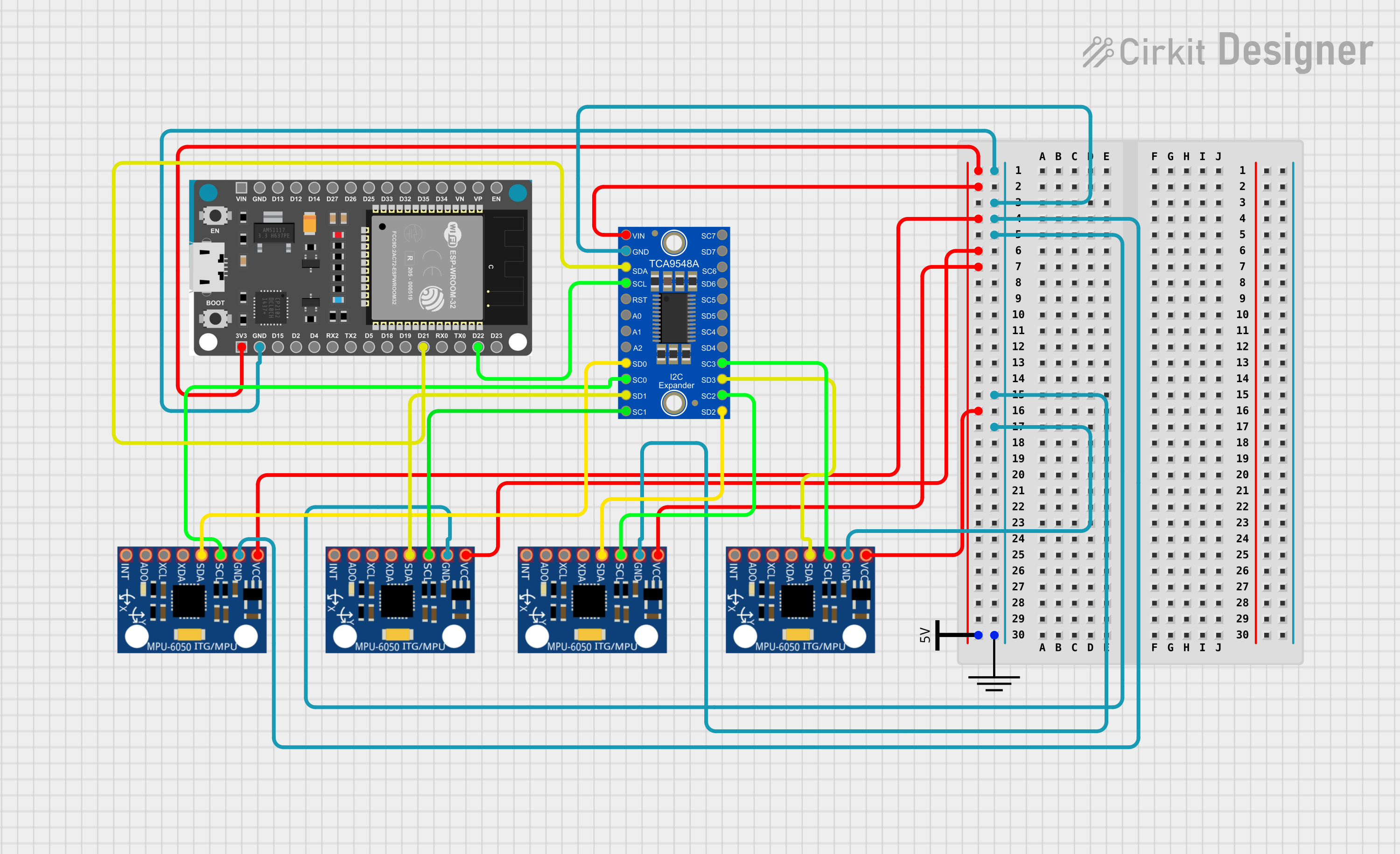 Open Project in Cirkit Designer
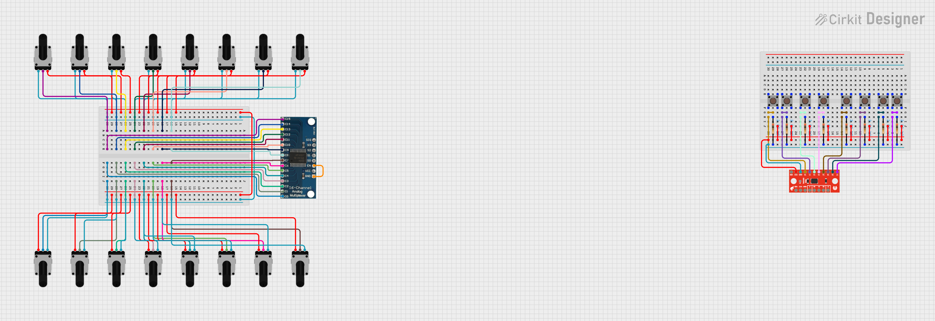 Open Project in Cirkit Designer
Explore Projects Built with PCA9548 8CH I2C MULTIPLEXER
Open Project in Cirkit DesignerOpen Project in Cirkit DesignerOpen Project in Cirkit DesignerOpen Project in Cirkit DesignerCommon Applications and Use Cases
- Expanding the number of I2C devices connected to a microcontroller.
- Managing multiple I2C devices with identical addresses.
- Isolating I2C devices to prevent bus conflicts.
- Applications in sensor arrays, data acquisition systems, and multi-device communication setups.
Technical Specifications
Key Technical Details
- Operating Voltage: 2.3V to 5.5V
- I2C Address Range: 0x70 to 0x77 (configurable via address pins)
- Maximum I2C Clock Frequency: 400 kHz (Fast-mode I2C)
- Number of Channels: 8
- Channel Isolation: Only the selected channel is active; others are isolated.
- Low Standby Current: Typically 1 µA
- ESD Protection: ±2000V (HBM)
- Package Options: TSSOP, SOIC, etc.
Pin Configuration and Descriptions
The PCA9548 typically comes in a 16-pin package. Below is the pinout and description:
| Pin | Name | Type | Description |
|---|---|---|---|
| 1 | A0 | Input | Address selection pin (LSB of I2C address). |
| 2 | A1 | Input | Address selection pin. |
| 3 | A2 | Input | Address selection pin (MSB of I2C address). |
| 4 | VSS | Power | Ground connection. |
| 5 | SDA | I/O | I2C data line (shared with master). |
| 6 | SCL | Input | I2C clock line (shared with master). |
| 7 | RESET | Input | Active-low reset pin to reset the device. |
| 8 | SD0 | I/O | I2C data line for channel 0. |
| 9 | SD1 | I/O | I2C data line for channel 1. |
| 10 | SD2 | I/O | I2C data line for channel 2. |
| 11 | SD3 | I/O | I2C data line for channel 3. |
| 12 | SD4 | I/O | I2C data line for channel 4. |
| 13 | SD5 | I/O | I2C data line for channel 5. |
| 14 | SD6 | I/O | I2C data line for channel 6. |
| 15 | SD7 | I/O | I2C data line for channel 7. |
| 16 | VDD | Power | Supply voltage (2.3V to 5.5V). |
Usage Instructions
How to Use the PCA9548 in a Circuit
- Power Supply: Connect the VDD pin to a 3.3V or 5V power source and the VSS pin to ground.
- I2C Address Configuration: Use the A0, A1, and A2 pins to set the I2C address. These pins can be connected to VDD (logic high) or VSS (logic low) to configure the address.
- I2C Bus Connection: Connect the SDA and SCL pins to the I2C bus of the microcontroller.
- Channel Selection: To communicate with a specific channel, send a control byte over the I2C bus. The control byte determines which channel is active.
- Reset: Optionally, connect the RESET pin to a GPIO pin on the microcontroller for manual reset functionality.
Important Considerations and Best Practices
- Pull-up Resistors: Ensure proper pull-up resistors are present on the SDA and SCL lines of the I2C bus.
- Channel Isolation: Only one channel can be active at a time. Ensure the correct channel is selected before communication.
- Address Conflicts: Use the address selection pins to avoid conflicts with other I2C devices on the bus.
- Voltage Compatibility: Ensure all connected devices operate within the same voltage range as the PCA9548.
Example Code for Arduino UNO
Below is an example of how to use the PCA9548 with an Arduino UNO to select a specific channel and communicate with a device:
#include <Wire.h>

// Define the I2C address of the PCA9548 (default is 0x70)
#define PCA9548_ADDRESS 0x70

void setup() {
  Wire.begin(); // Initialize I2C communication
  Serial.begin(9600); // Initialize serial communication for debugging
}

void loop() {
  // Select channel 0 on the PCA9548
  selectChannel(0);

  // Example: Communicate with a device on channel 0
  Wire.beginTransmission(0x40); // Replace 0x40 with the I2C address of your device
  Wire.write(0x00); // Example: Write a command or register address
  Wire.endTransmission();

  delay(1000); // Wait for 1 second before switching channels
}

// Function to select a specific channel on the PCA9548
void selectChannel(uint8_t channel) {
  if (channel > 7) {
    Serial.println("Invalid channel! Must be between 0 and 7.");
    return;
  }

  Wire.beginTransmission(PCA9548_ADDRESS);
  Wire.write(1 << channel); // Send control byte to select the channel
  Wire.endTransmission();

  Serial.print("Channel ");
  Serial.print(channel);
  Serial.println(" selected.");
}
Troubleshooting and FAQs
Common Issues and Solutions
No Communication with Devices:
- Ensure the correct channel is selected before attempting communication.
- Verify that the I2C address of the PCA9548 matches the address configured via the A0, A1, and A2 pins.
- Check for proper pull-up resistors on the SDA and SCL lines.
Bus Conflicts:
- Ensure only one channel is active at a time.
- Verify that no two devices on the same channel share the same I2C address.
Device Not Responding:
- Check the power supply connections to the PCA9548 and connected devices.
- Verify that the RESET pin is not being held low unintentionally.
Incorrect Channel Selection:
- Double-check the control byte sent to the PCA9548. Each bit corresponds to a specific channel.
FAQs
Q: Can I use multiple PCA9548 devices on the same I2C bus?
A: Yes, you can use up to 8 PCA9548 devices on the same bus by configuring their I2C addresses using the A0, A1, and A2 pins.
Q: What happens if no channel is selected?
A: If no channel is selected (control byte is 0x00), all channels are isolated, and no communication will occur.
Q: Is the PCA9548 compatible with 5V logic?
A: Yes, the PCA9548 supports operating voltages from 2.3V to 5.5V, making it compatible with both 3.3V and 5V systems.