How to Use oled 2.4 inch: Examples, Pinouts, and Specs
Introduction
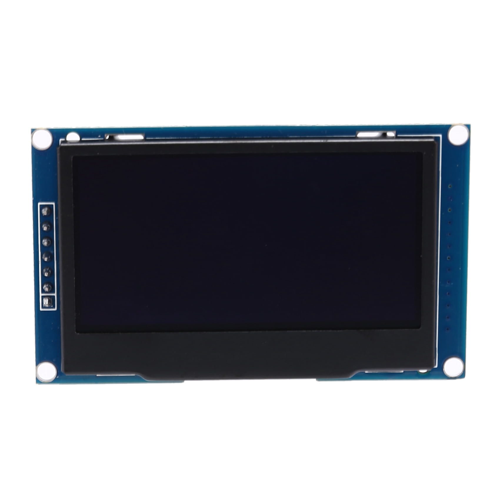
The OLED 2.4-inch display, manufactured by Arduino (Part ID: UNO), is a high-resolution organic light-emitting diode display. It offers vibrant colors, sharp contrast, and low power consumption, making it ideal for a variety of applications. This display is commonly used in small electronic devices for user interfaces, graphical outputs, and data visualization.
Explore Projects Built with oled 2.4 inch

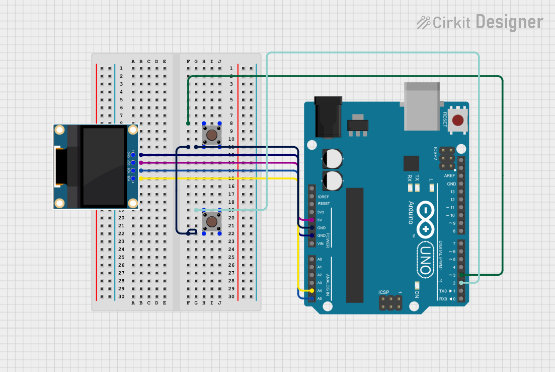

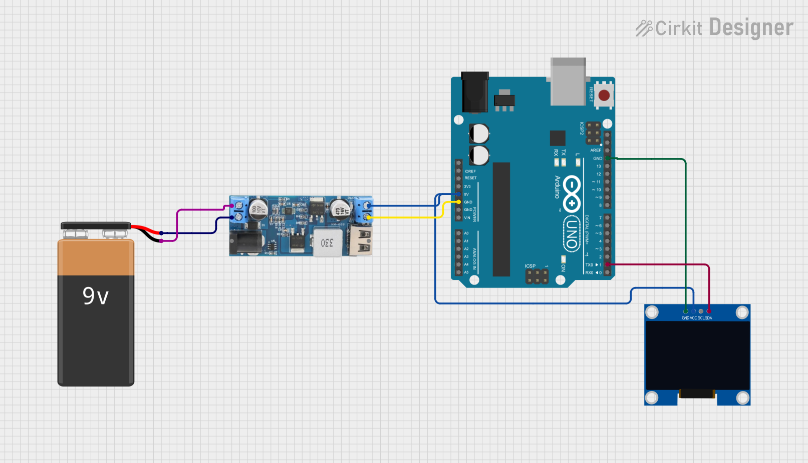
Explore Projects Built with oled 2.4 inch
Common Applications and Use Cases
- User interfaces for embedded systems
- Graphical data visualization (e.g., charts, gauges)
- Portable devices and wearables
- IoT dashboards
- Gaming consoles and handheld devices
Technical Specifications
The following table outlines the key technical details of the OLED 2.4-inch display:
| Parameter | Specification |
|---|---|
| Display Type | OLED |
| Screen Size | 2.4 inches |
| Resolution | 240 x 320 pixels |
| Color Depth | 16-bit (65,536 colors) |
| Interface | SPI/I2C |
| Operating Voltage | 3.3V - 5V |
| Operating Current | ~20mA (typical) |
| Viewing Angle | ~160° |
| Operating Temperature | -20°C to 70°C |
| Dimensions | 60mm x 42mm x 4mm |
Pin Configuration and Descriptions
The OLED 2.4-inch display typically uses an SPI interface. Below is the pin configuration:
| Pin Name | Pin Number | Description |
|---|---|---|
| VCC | 1 | Power supply (3.3V or 5V) |
| GND | 2 | Ground |
| SCL (CLK) | 3 | Serial clock input |
| SDA (MOSI) | 4 | Serial data input |
| RES | 5 | Reset pin (active low) |
| DC | 6 | Data/Command control pin |
| CS | 7 | Chip select (active low) |
| NC | 8 | Not connected (reserved for future use) |
Usage Instructions
How to Use the Component in a Circuit
- Power Supply: Connect the VCC pin to a 3.3V or 5V power source and the GND pin to ground.
- Communication Interface: Use the SPI interface for communication. Connect the SCL, SDA, RES, DC, and CS pins to the corresponding pins on your microcontroller.
- Initialization: Ensure the display is properly initialized in your code before sending data.
- Data Transmission: Use the SPI protocol to send commands and data to the display.
Important Considerations and Best Practices
- Voltage Compatibility: Ensure the display operates within the specified voltage range (3.3V to 5V). Use a level shifter if your microcontroller operates at 5V logic.
- Reset Pin: Always connect the RES pin to your microcontroller to allow proper initialization.
- Library Support: Use Arduino libraries such as
Adafruit_GFXandAdafruit_SSD1306for easier integration. - Avoid Static Damage: Handle the display carefully to avoid damage from electrostatic discharge (ESD).
Example Code for Arduino UNO
Below is an example of how to use the OLED 2.4-inch display with an Arduino UNO:
#include <Adafruit_GFX.h>       // Graphics library for OLED
#include <Adafruit_SSD1306.h>   // OLED driver library

#define SCREEN_WIDTH 240        // OLED width in pixels
#define SCREEN_HEIGHT 320       // OLED height in pixels

// Define OLED pins
#define OLED_MOSI 11            // Data pin (SDA)
#define OLED_CLK 13             // Clock pin (SCL)
#define OLED_DC 9               // Data/Command pin
#define OLED_CS 10              // Chip Select pin
#define OLED_RESET 8            // Reset pin

// Create an instance of the display
Adafruit_SSD1306 display(SCREEN_WIDTH, SCREEN_HEIGHT, &SPI, OLED_DC, OLED_RESET, OLED_CS);

void setup() {
  // Initialize serial communication for debugging
  Serial.begin(9600);

  // Initialize the OLED display
  if (!display.begin(SSD1306_I2C_ADDRESS, OLED_RESET)) {
    Serial.println(F("OLED initialization failed!"));
    while (true); // Halt execution if initialization fails
  }

  // Clear the display buffer
  display.clearDisplay();

  // Display a welcome message
  display.setTextSize(1);         // Set text size
  display.setTextColor(SSD1306_WHITE); // Set text color
  display.setCursor(0, 0);        // Set cursor position
  display.println(F("Hello, OLED!"));
  display.display();              // Update the display
}

void loop() {
  // Add your code here to update the display
}
Troubleshooting and FAQs
Common Issues and Solutions
Display Not Turning On:
- Verify the power supply connections (VCC and GND).
- Check if the RES pin is properly connected and initialized in the code.
No Output on the Screen:
- Ensure the SPI connections (SCL, SDA, DC, CS) are correct.
- Confirm that the correct library and initialization settings are used.
Flickering or Distorted Display:
- Check for loose connections or poor soldering.
- Ensure the power supply is stable and within the specified range.
Library Errors:
- Make sure the
Adafruit_GFXandAdafruit_SSD1306libraries are installed and up to date. - Verify that the correct display driver is selected in the code.
- Make sure the
FAQs
Q: Can I use this display with a 5V microcontroller?
A: Yes, the display supports 3.3V to 5V operation. However, ensure proper logic level shifting if required.
Q: Is the display compatible with I2C?
A: While this display primarily uses SPI, some variants may support I2C. Check the datasheet for details.
Q: How do I display images on the screen?
A: Use the Adafruit_GFX library to draw bitmaps. Convert your image to a compatible format using online tools or software.
Q: Can I daisy-chain multiple displays?
A: No, the SPI interface does not support daisy-chaining. Each display requires a separate chip select (CS) pin.
By following this documentation, you can effectively integrate and troubleshoot the OLED 2.4-inch display in your projects.