Cirkit Designer Logo
Cirkit Designer
Your all-in-one circuit design IDE
Home / 
Component Documentation

How to Use UPS BATTERY: Examples, Pinouts, and Specs

Image of UPS BATTERY
Cirkit Designer LogoDesign with UPS BATTERY in Cirkit Designer

Introduction

A UPS (Uninterruptible Power Supply) battery is an essential component in power backup systems. It is designed to provide emergency power to a load, typically critical electronic equipment, when the input power source, usually the mains power, fails. UPS batteries are widely used in various settings, including data centers, hospitals, telecommunications, and residential applications, ensuring continuity of operation and protection against data loss or hardware damage due to power disruptions.

Explore Projects Built with UPS BATTERY

Use Cirkit Designer to design, explore, and prototype these projects online. Some projects support real-time simulation. Click "Open Project" to start designing instantly!
12V UPS System with Dual 18650 Li-ion Battery Backup and Voltage Regulation
Image of Power supply: A project utilizing UPS BATTERY in a practical application
This circuit is designed to provide an uninterruptible power supply (UPS) system with a 12V DC output. It includes a 12V 5A power supply connected to an AC source through a toggle switch, which charges a pair of 18650 Li-ion batteries via a voltage regulator (XL4016). The UPS module ensures a continuous power supply to the load by switching between the power supply and the battery bank.
Cirkit Designer LogoOpen Project in Cirkit Designer
Battery-Powered UPS with Step-Down Buck Converter and BMS
Image of Mini ups: A project utilizing UPS BATTERY in a practical application
This circuit is a power management system that steps down a 240V AC input to a lower DC voltage using a buck converter, which then powers a 40W UPS. The UPS is controlled by a rocker switch and is backed up by a battery management system (BMS) connected to three 3.7V batteries in series, ensuring continuous power supply.
Cirkit Designer LogoOpen Project in Cirkit Designer
Battery-Powered UPS System with Waveshare UPS 3S and Solar Charger
Image of Copy of s: A project utilizing UPS BATTERY in a practical application
This circuit is a power management system that integrates a 12V power supply, a solar charger power bank, and multiple Li-ion batteries to provide a stable power output. The Waveshare UPS 3S manages the input from the power sources and batteries, ensuring continuous power delivery. The MRB045 module is used to interface the solar charger with the rest of the system.
Cirkit Designer LogoOpen Project in Cirkit Designer
Solar-Powered UPS with Multiple Battery Management
Image of schematic: A project utilizing UPS BATTERY in a practical application
This circuit is designed to integrate a solar power system with multiple 12V batteries and a UPS module for uninterrupted power supply. The solar panel charges the batteries through a charge controller, which is protected by DC MCBs. The UPS modules are connected to the batteries and provide a regulated DC output, which is then adjusted by an XL4016 DC-DC converter module.
Cirkit Designer LogoOpen Project in Cirkit Designer

Explore Projects Built with UPS BATTERY

Use Cirkit Designer to design, explore, and prototype these projects online. Some projects support real-time simulation. Click "Open Project" to start designing instantly!
Image of Power supply: A project utilizing UPS BATTERY in a practical application
12V UPS System with Dual 18650 Li-ion Battery Backup and Voltage Regulation
This circuit is designed to provide an uninterruptible power supply (UPS) system with a 12V DC output. It includes a 12V 5A power supply connected to an AC source through a toggle switch, which charges a pair of 18650 Li-ion batteries via a voltage regulator (XL4016). The UPS module ensures a continuous power supply to the load by switching between the power supply and the battery bank.
Cirkit Designer LogoOpen Project in Cirkit Designer
Image of Mini ups: A project utilizing UPS BATTERY in a practical application
Battery-Powered UPS with Step-Down Buck Converter and BMS
This circuit is a power management system that steps down a 240V AC input to a lower DC voltage using a buck converter, which then powers a 40W UPS. The UPS is controlled by a rocker switch and is backed up by a battery management system (BMS) connected to three 3.7V batteries in series, ensuring continuous power supply.
Cirkit Designer LogoOpen Project in Cirkit Designer
Image of Copy of s: A project utilizing UPS BATTERY in a practical application
Battery-Powered UPS System with Waveshare UPS 3S and Solar Charger
This circuit is a power management system that integrates a 12V power supply, a solar charger power bank, and multiple Li-ion batteries to provide a stable power output. The Waveshare UPS 3S manages the input from the power sources and batteries, ensuring continuous power delivery. The MRB045 module is used to interface the solar charger with the rest of the system.
Cirkit Designer LogoOpen Project in Cirkit Designer
Image of schematic: A project utilizing UPS BATTERY in a practical application
Solar-Powered UPS with Multiple Battery Management
This circuit is designed to integrate a solar power system with multiple 12V batteries and a UPS module for uninterrupted power supply. The solar panel charges the batteries through a charge controller, which is protected by DC MCBs. The UPS modules are connected to the batteries and provide a regulated DC output, which is then adjusted by an XL4016 DC-DC converter module.
Cirkit Designer LogoOpen Project in Cirkit Designer

Technical Specifications

General Characteristics

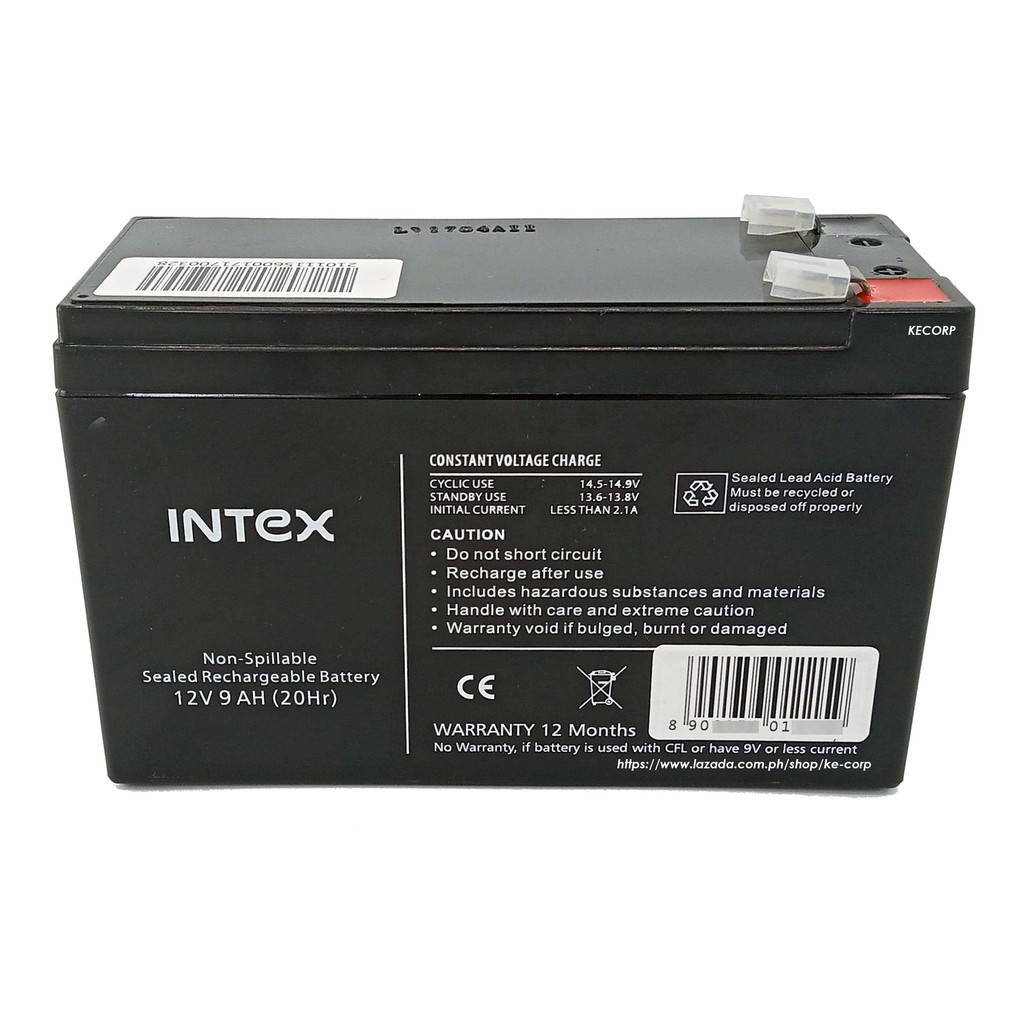
  • Battery Type: Sealed Lead Acid (SLA)/Lithium-ion (Li-ion)/Nickel-Cadmium (NiCd)/Nickel-Metal Hydride (NiMH)
  • Nominal Voltage: 12V/24V/48V (varies by model and application)
  • Capacity: Rated in ampere-hours (Ah), commonly ranging from 7Ah to 200Ah
  • Design Life: 3-5 years for SLA, up to 10 years for Li-ion (varies by usage and environment)
  • Operating Temperature Range: Typically 0°C to 40°C

Electrical Characteristics

  • Charge Voltage: Varies by battery chemistry and manufacturer's specifications
  • Maximum Charging Current: Depends on battery capacity and manufacturer's recommendations
  • Discharge Cut-off Voltage: Determined by the UPS system to prevent deep discharge
  • Energy Density: Higher for Li-ion compared to SLA

Pin Configuration and Descriptions

Pin No. Description Note
1 Positive Terminal Connect to the positive of the load/UPS
2 Negative Terminal Connect to the negative of the load/UPS

Note: UPS batteries typically have two terminals, positive and negative. Some models may include additional terminals for temperature sensing or battery management systems.

Usage Instructions

Installation

  1. Safety First: Always wear protective gear and follow the manufacturer's safety instructions.
  2. Orientation: Install the battery in the correct orientation as indicated by the '+' and '-' symbols.
  3. Connection: Use appropriate gauge wires and connectors to ensure a secure and low-resistance connection.
  4. Charging: Before first use, charge the battery according to the manufacturer's instructions.

Integration with UPS

  1. Compatibility: Ensure the battery voltage and capacity match the UPS system requirements.
  2. Wiring: Connect the battery terminals to the corresponding UPS terminals, observing proper polarity.
  3. Configuration: Set up the UPS system settings to match the battery type and capacity for optimal charging and discharging.

Best Practices

  • Maintenance: Regularly check the battery voltage and physical condition.
  • Storage: Store in a cool, dry place and periodically charge if not in use for extended periods.
  • Recycling: Dispose of batteries according to local regulations and recycle when possible.

Troubleshooting and FAQs

Common Issues

  • UPS not providing backup power: Check battery connections, charge level, and health.
  • Battery not charging: Ensure the UPS charging system is functioning and the battery is not at the end of its life.
  • Reduced backup time: This may indicate battery aging or a higher load than the battery is rated for.

FAQs

Q: How often should I replace my UPS battery? A: The replacement period varies by battery type and usage but typically ranges from 3 to 5 years.

Q: Can I increase my UPS backup time? A: Yes, by using a battery with a higher capacity or adding additional batteries in parallel, if supported by the UPS.

Q: Is it safe to replace the UPS battery myself? A: Yes, if you follow the manufacturer's instructions and safety precautions. If unsure, seek professional assistance.

Example Code for Arduino UPS Monitoring

// This example assumes the use of an Arduino UNO to monitor a UPS battery voltage.

const int batteryPin = A0; // Analog pin connected to battery voltage divider

void setup() {
  Serial.begin(9600);
}

void loop() {
  int sensorValue = analogRead(batteryPin); // Read the analog value
  float voltage = sensorValue * (5.0 / 1023.0) * (11.0); // Convert to voltage
  Serial.print("Battery Voltage: ");
  Serial.println(voltage);
  delay(1000); // Wait for 1 second before the next read
}

Note: The voltage divider factor (11.0) in the code should be adjusted based on the actual resistors used in the voltage divider circuit connected to the battery.

Remember to never exceed the voltage rating of the Arduino analog input pins (5V for Arduino UNO). Always use a voltage divider or level shifter when necessary.

This documentation provides a comprehensive guide to understanding, using, and maintaining a UPS battery. For further assistance, consult the manufacturer's datasheet and user manual.