How to Use Sparkfun Configurable OpAmp Board - TSH82: Examples, Pinouts, and Specs
Introduction
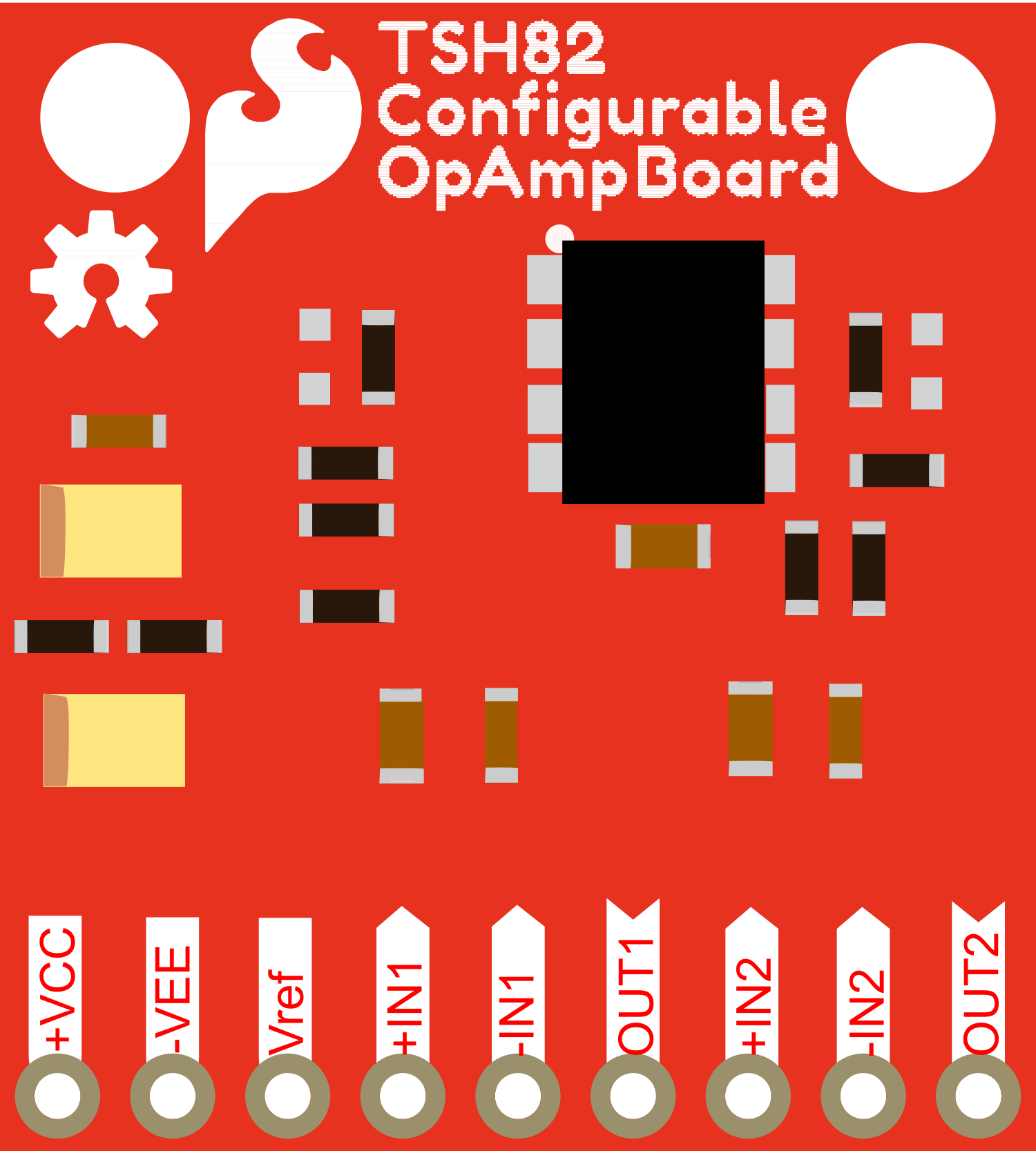
The Sparkfun Configurable OpAmp Board featuring the TSH82 operational amplifier is a versatile and adjustable component designed for a variety of electronic applications. This board is particularly useful in audio amplification and signal conditioning due to its configurable gain and bandwidth settings. The TSH82 is a dual operational amplifier, which means it contains two independent op-amps in a single package, making it ideal for stereo audio applications or dual-channel signal processing.
Explore Projects Built with Sparkfun Configurable OpAmp Board - TSH82
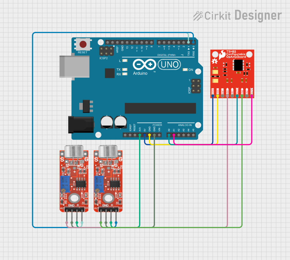
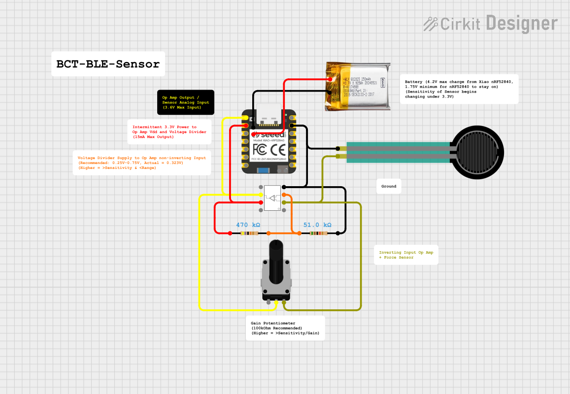
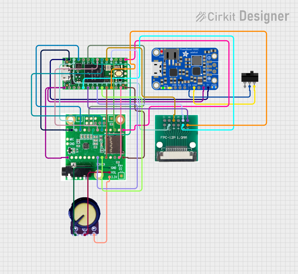

Explore Projects Built with Sparkfun Configurable OpAmp Board - TSH82
Common Applications and Use Cases
- Audio amplification and pre-amplification
- Active filters and equalizers
- Signal conditioning
- Analog signal mixing
- Sensor amplification and interfacing
Technical Specifications
Key Technical Details
- Supply Voltage (Vcc): ±2.5V to ±6V
- Input Offset Voltage: 3mV max
- Input Bias Current: 1pA typical
- Output Short-Circuit Current: 40mA typical
- Gain Bandwidth Product: 75MHz typical
- Slew Rate: 27V/µs typical
- Operating Temperature Range: -40°C to +125°C
Pin Configuration and Descriptions
| Pin Number | Description | Notes |
|---|---|---|
| 1 | Output A | Output of op-amp A |
| 2 | Inverting Input A | Negative input for op-amp A |
| 3 | Non-Inverting Input A | Positive input for op-amp A |
| 4 | Vee (Negative Supply) | Negative power supply |
| 5 | Non-Inverting Input B | Positive input for op-amp B |
| 6 | Inverting Input B | Negative input for op-amp B |
| 7 | Output B | Output of op-amp B |
| 8 | Vcc (Positive Supply) | Positive power supply |
Usage Instructions
How to Use the Component in a Circuit
Power Supply: Connect the Vcc and Vee pins to your power supply, ensuring that the voltage levels are within the specified range for the TSH82.
Input Signal: Connect the signal you wish to amplify or condition to the non-inverting input (pin 3 for op-amp A or pin 5 for op-amp B) of the desired op-amp.
Feedback Loop: To set the gain of the op-amp, connect a feedback resistor between the output (pin 1 for op-amp A or pin 7 for op-amp B) and the inverting input (pin 2 for op-amp A or pin 6 for op-amp B). You can also add a resistor from the inverting input to ground to create a voltage divider, which will further define the gain.
Output: The amplified or conditioned signal can be taken from the output pin of the respective op-amp.
Important Considerations and Best Practices
- Ensure that the power supply voltage does not exceed the maximum ratings of the TSH82 to prevent damage.
- Use bypass capacitors close to the power supply pins to minimize noise and stabilize the power supply.
- Keep the input and output signal paths as short as possible to reduce noise pickup and potential oscillations.
- When configuring the gain, be aware of the bandwidth-gain product to avoid unintentional bandwidth limitations.
Troubleshooting and FAQs
Common Issues Users Might Face
Oscillations or Instability: This can occur if the feedback network is not properly designed or if there is insufficient power supply decoupling. Check the feedback resistors and ensure that bypass capacitors are in place.
Low Output Signal: If the output signal is lower than expected, verify that the gain has been set correctly and that the input signal is within the expected range.
Distorted Output Signal: This may be caused by exceeding the input voltage range or the power supply voltage range. Ensure that all voltages are within the specified limits.
Solutions and Tips for Troubleshooting
- Double-check all connections and ensure that the component is correctly oriented in the circuit.
- Use an oscilloscope to monitor the input and output signals to verify that the op-amp is functioning as expected.
- If you encounter noise or interference, consider adding shielding to your circuit or re-routing signal paths away from sources of noise.
FAQs
Q: Can I use a single power supply with the TSH82? A: Yes, the TSH82 can be used with a single power supply, but you will need to create a virtual ground at half the supply voltage for the inputs and outputs to function correctly.
Q: What is the maximum gain I can set on the TSH82? A: The maximum gain is limited by the gain-bandwidth product. As you increase the gain, the bandwidth will decrease accordingly.
Q: How do I configure the TSH82 for a non-inverting amplifier? A: Connect the input signal to the non-inverting input and use a feedback resistor from the output to the inverting input, with another resistor from the inverting input to ground.
Q: Can the TSH82 be used for differential signal amplification? A: Yes, the TSH82 can be configured as a differential amplifier by appropriately connecting the inverting and non-inverting inputs of both op-amps.
Example Arduino UNO Connection and Code
// Example code for interfacing the TSH82 OpAmp with an Arduino UNO
// This example assumes the OpAmp is configured for a gain of 10

const int analogInputPin = A0; // Connect the OpAmp output to Arduino analog pin A0
const int ledPin = 9;          // Connect an LED to pin 9 (with a resistor)

void setup() {
  pinMode(ledPin, OUTPUT);
  Serial.begin(9600);
}

void loop() {
  int sensorValue = analogRead(analogInputPin); // Read the amplified signal
  float voltage = sensorValue * (5.0 / 1023.0); // Convert to voltage
  Serial.print("Voltage: ");
  Serial.println(voltage);
  analogWrite(ledPin, sensorValue / 4); // Scale the value for the LED
  delay(100); // Wait for 100 milliseconds
}
Remember to adjust the code to match the specific configuration of your TSH82 OpAmp board. The example provided is a simple demonstration of reading an amplified signal and using it to control the brightness of an LED.