How to Use SSD1306: Examples, Pinouts, and Specs
Introduction
The SSD1306 is a monochrome OLED display driver designed to control OLED displays with resolutions up to 128x64 pixels. Manufactured by Arduino with the part ID "Uno," this versatile component supports both I2C and SPI communication protocols, making it ideal for integration into a wide range of embedded systems. Its compact size, low power consumption, and high contrast make it a popular choice for displaying text, graphics, and images in various applications.
Explore Projects Built with SSD1306
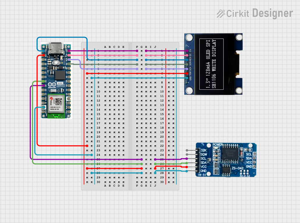
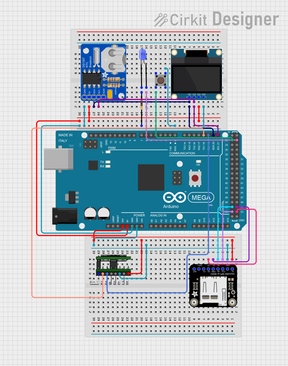

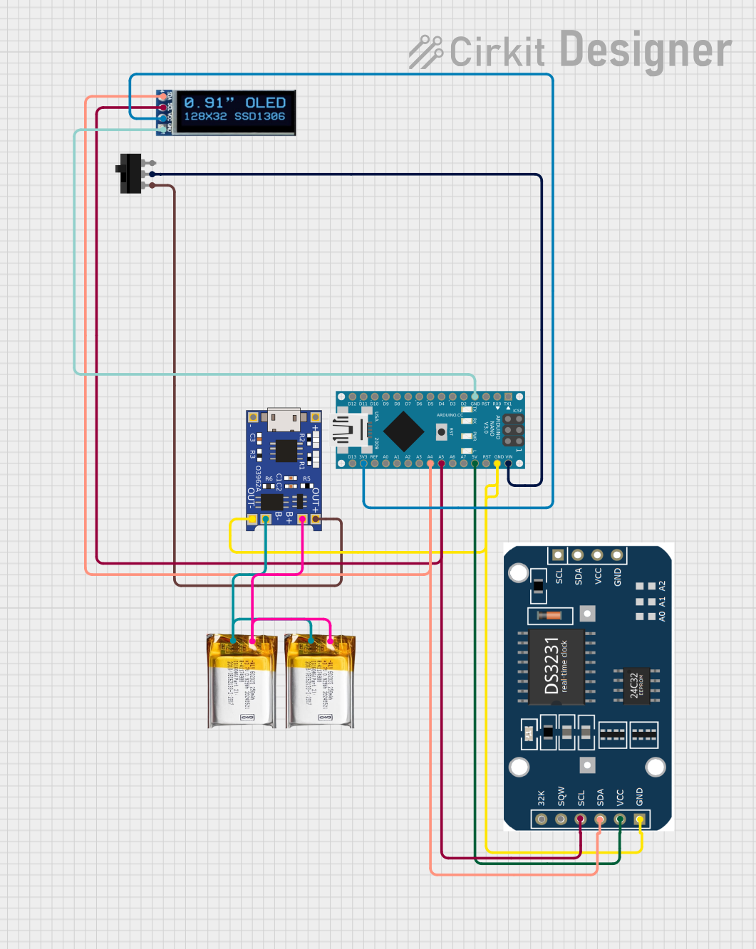
Explore Projects Built with SSD1306
Common Applications and Use Cases
- Wearable devices and smartwatches
- IoT devices and home automation systems
- Portable medical devices
- Industrial control panels
- Hobbyist and educational projects with microcontrollers like Arduino
Technical Specifications
The SSD1306 is a highly capable display driver with the following key specifications:
| Parameter | Value |
|---|---|
| Display Resolution | 128x64 pixels |
| Communication Protocols | I2C, SPI |
| Operating Voltage | 3.3V to 5V |
| Current Consumption | ~20mA (varies with brightness) |
| Display Type | Monochrome OLED |
| Pixel Color | White or Blue (depending on model) |
| Operating Temperature | -40°C to +85°C |
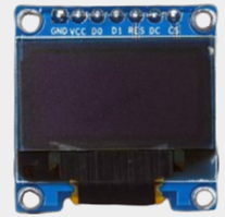
Pin Configuration and Descriptions
The SSD1306 module typically has the following pin configuration:
I2C Mode Pinout
| Pin Name | Description |
|---|---|
| VCC | Power supply (3.3V or 5V) |
| GND | Ground |
| SCL | Serial Clock Line for I2C |
| SDA | Serial Data Line for I2C |
SPI Mode Pinout
| Pin Name | Description |
|---|---|
| VCC | Power supply (3.3V or 5V) |
| GND | Ground |
| SCK | Serial Clock Line for SPI |
| MOSI | Master Out Slave In (Data Line) |
| CS | Chip Select (Active Low) |
| DC | Data/Command Control |
| RES | Reset (Active Low) |
Usage Instructions
How to Use the SSD1306 in a Circuit
- Power Supply: Connect the VCC pin to a 3.3V or 5V power source and the GND pin to ground.
- Communication Protocol: Choose between I2C or SPI based on your application. For I2C, connect the SCL and SDA pins to the corresponding pins on your microcontroller. For SPI, connect SCK, MOSI, CS, DC, and RES as required.
- Pull-Up Resistors: If using I2C, ensure pull-up resistors (typically 4.7kΩ) are connected to the SCL and SDA lines.
- Initialization: Use a compatible library (e.g., Adafruit SSD1306 library) to initialize and control the display.
Important Considerations and Best Practices
- Voltage Compatibility: Ensure the display module's voltage matches your microcontroller's logic level (3.3V or 5V).
- Contrast and Brightness: Adjust these settings in your code to optimize power consumption and display clarity.
- Avoid Static Damage: Handle the module carefully to prevent electrostatic discharge (ESD) damage.
- Mounting: Secure the module properly to avoid stress on the pins or PCB.
Example Code for Arduino UNO
Below is an example of how to use the SSD1306 with an Arduino UNO via I2C:
#include <Wire.h>
#include <Adafruit_GFX.h>
#include <Adafruit_SSD1306.h>

// Define the OLED display width and height
#define SCREEN_WIDTH 128
#define SCREEN_HEIGHT 64

// Create an SSD1306 display object connected via I2C
Adafruit_SSD1306 display(SCREEN_WIDTH, SCREEN_HEIGHT, &Wire, -1);

void setup() {
  // Initialize serial communication for debugging
  Serial.begin(9600);

  // Initialize the SSD1306 display
  if (!display.begin(SSD1306_I2C_ADDRESS, 0x3C)) {
    Serial.println(F("SSD1306 allocation failed"));
    for (;;); // Halt execution if initialization fails
  }

  // Clear the display buffer
  display.clearDisplay();

  // Display a welcome message
  display.setTextSize(1); // Set text size to 1 (smallest)
  display.setTextColor(SSD1306_WHITE); // Set text color to white
  display.setCursor(0, 0); // Set cursor to top-left corner
  display.println(F("Hello, SSD1306!")); // Print message
  display.display(); // Update the display with the buffer content
}

void loop() {
  // Add your code here to update the display dynamically
}
Troubleshooting and FAQs
Common Issues and Solutions
Display Not Turning On:
- Verify the power supply connections (VCC and GND).
- Check if the I2C or SPI connections are correct.
- Ensure the correct I2C address (default is 0x3C) is used in the code.
Flickering or Unstable Display:
- Ensure proper pull-up resistors are connected for I2C communication.
- Check for loose or faulty wiring.
Text or Graphics Not Displaying Properly:
- Verify that the correct resolution (128x64) is set in the code.
- Ensure the display buffer is cleared before updating the screen.
Library Errors:
- Ensure the Adafruit SSD1306 and Adafruit GFX libraries are installed in the Arduino IDE.
- Update the libraries to the latest version if issues persist.
FAQs
Q: Can the SSD1306 display grayscale images?
A: No, the SSD1306 is a monochrome display driver and supports only black and white pixels.
Q: What is the maximum cable length for I2C communication?
A: The maximum length depends on the pull-up resistor values and the operating frequency, but it is typically limited to 1 meter for reliable communication.
Q: Can I use the SSD1306 with a 3.3V microcontroller?
A: Yes, the SSD1306 is compatible with both 3.3V and 5V logic levels.
Q: How do I switch between I2C and SPI modes?
A: The mode is determined by the hardware configuration of the module. Refer to the module's datasheet or documentation for specific instructions.