How to Use Arduino GIGA R1 WIFI: Examples, Pinouts, and Specs
Introduction
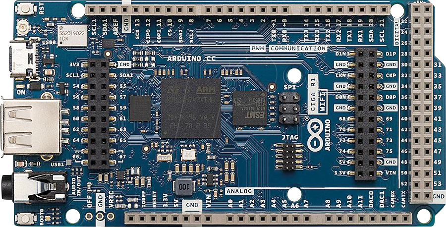
The Arduino GIGA R1 WIFI is a versatile and powerful microcontroller board designed for hobbyists, educators, and professionals alike. Based on the Atmega2560 chip, it offers a substantial increase in memory and processing power compared to other Arduino boards. With integrated Wi-Fi and Bluetooth connectivity, it enables users to create connected projects with ease. Common applications include IoT devices, automation systems, and complex robotics.
Explore Projects Built with Arduino GIGA R1 WIFI
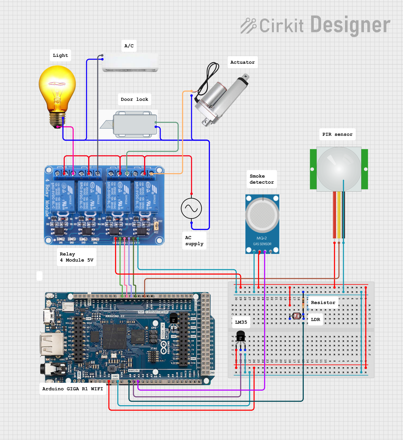
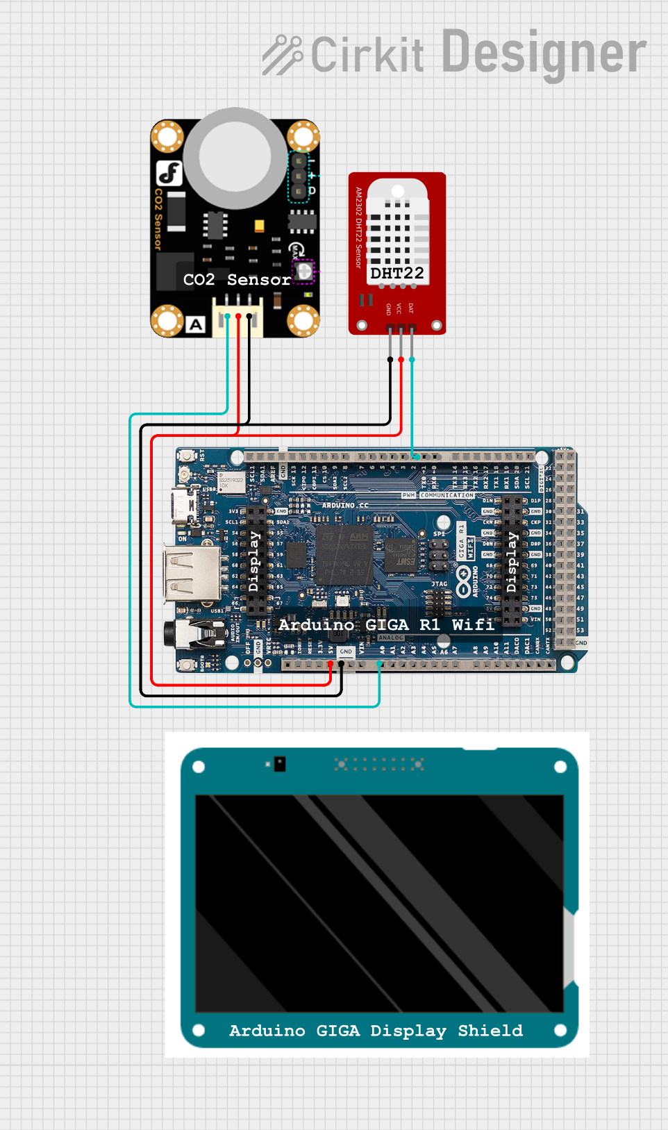
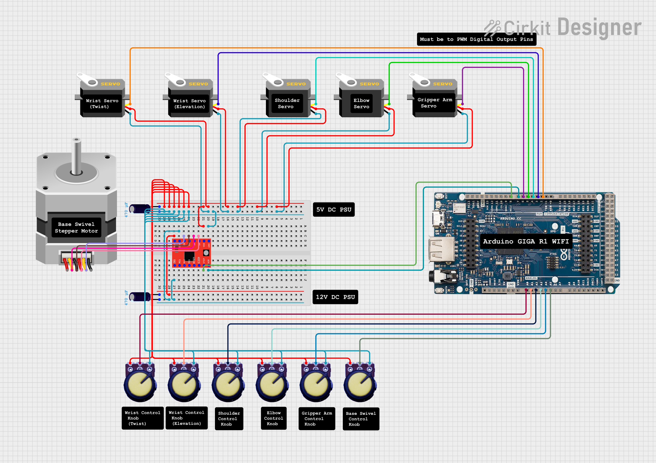
Explore Projects Built with Arduino GIGA R1 WIFI
Technical Specifications
Key Technical Details
- Microcontroller: ATmega2560
- Operating Voltage: 5V
- Input Voltage (recommended): 7-12V
- Input Voltage (limit): 6-20V
- Digital I/O Pins: 54 (of which 15 provide PWM output)
- Analog Input Pins: 16
- DC Current per I/O Pin: 20 mA
- DC Current for 3.3V Pin: 50 mA
- Flash Memory: 256 KB of which 8 KB used by bootloader
- SRAM: 8 KB
- EEPROM: 4 KB
- Clock Speed: 16 MHz
- LED_BUILTIN: Pin 13
- Wi-Fi: u-blox NINA-W102 (802.11 b/g/n)
- Bluetooth: BLE
- USB: Micro-USB
Pin Configuration and Descriptions
| Pin Number | Function | Description |
|---|---|---|
| 1-54 | Digital I/O | Digital input/output pins, PWM on 15 pins |
| A0-A15 | Analog Input | Analog input pins |
| RX0, TX0 | Serial Ports | Serial communication pins |
| SDA, SCL | I2C | I2C communication pins |
| SCK, MISO, MOSI | SPI | SPI communication pins |
| RESET | Reset | Reset pin |
| 3V3, 5V, GND, VIN | Power | Power supply and ground pins |
Usage Instructions
Integrating with a Circuit
- Powering the Board: Connect a 7-12V power supply to the VIN and GND pins, or plug in the Micro-USB cable to a power source or computer.
- Connecting I/O: Attach sensors, actuators, or other components to the digital and analog pins as required for your project.
- Programming: Use the Arduino IDE to write and upload sketches to the board via the Micro-USB connection.
Best Practices
- Ensure that the power supply is within the recommended limits to prevent damage.
- Do not draw more than 20 mA from any I/O pin.
- Use external power sources when connecting components that require more current than the board can provide.
- Always disconnect the board from power sources before making or altering connections.
Troubleshooting and FAQs
Common Issues
- Board not recognized: Ensure drivers are installed and the Micro-USB cable is functioning.
- Sketch not uploading: Check the selected board and port in the Arduino IDE, and ensure the bootloader is operational.
- Wi-Fi/Bluetooth not working: Verify that the antennas are intact and the firmware is up to date.
Solutions and Tips
- Driver Installation: Download and install the latest drivers from the Arduino website.
- Bootloader Issues: If necessary, reflash the bootloader using an external programmer.
- Firmware Updates: Use the Arduino IDE to update the Wi-Fi and Bluetooth module firmware.
Code Example for Arduino UNO
Here is a simple example of how to blink the onboard LED using the Arduino GIGA R1 WIFI:
// Define the LED pin
const int ledPin = 13;

void setup() {
  // Initialize the LED pin as an output
  pinMode(ledPin, OUTPUT);
}

void loop() {
  // Turn the LED on
  digitalWrite(ledPin, HIGH);
  // Wait for a second
  delay(1000);
  // Turn the LED off
  digitalWrite(ledPin, LOW);
  // Wait for a second
  delay(1000);
}
Remember to select the correct board from the Tools > Board menu in the Arduino IDE before uploading the sketch.
For more advanced examples involving Wi-Fi and Bluetooth functionalities, refer to the examples provided in the Arduino IDE after installing the board's package.
Conclusion
The Arduino GIGA R1 WIFI is a robust platform for developing complex and connected projects. With its extensive I/O capabilities and wireless features, it opens up a world of possibilities for creators. By following the guidelines and best practices outlined in this documentation, users can ensure a successful and enjoyable experience with the Arduino GIGA R1 WIFI.