How to Use 12V solenoid lock: Examples, Pinouts, and Specs
Introduction
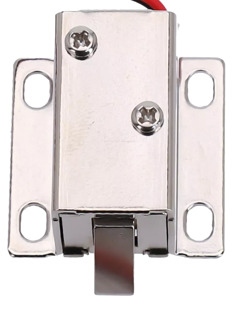
The 12V solenoid lock is an electromechanical device designed to provide secure access control. It operates by using a solenoid to control the locking mechanism, which is activated when a 12V DC power supply is applied. This component is widely used in applications requiring automated locking and unlocking, such as vending machines, lockers, cabinets, and access control systems.
Explore Projects Built with 12V solenoid lock
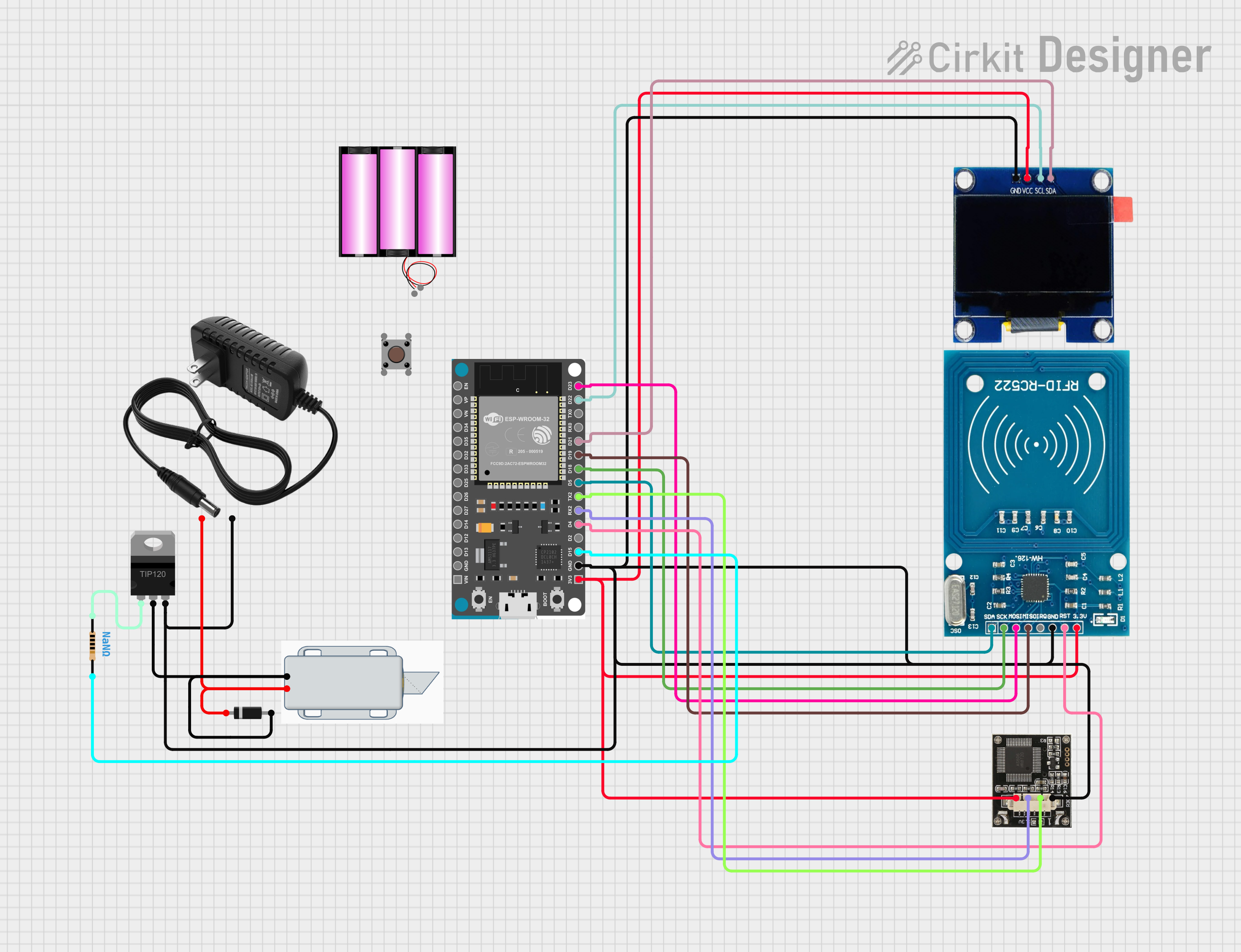
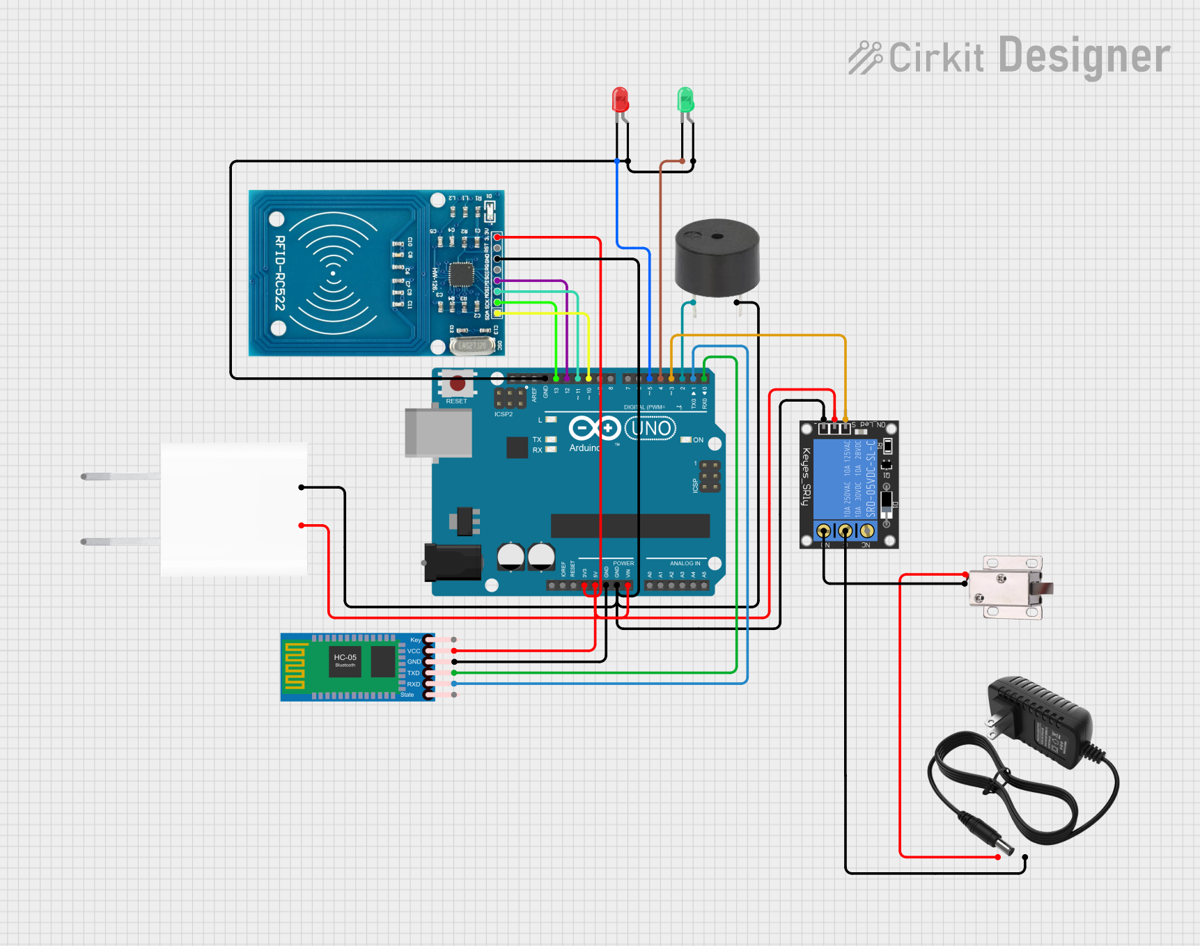
Explore Projects Built with 12V solenoid lock
Common Applications and Use Cases
- Automated door locking systems
- Secure storage compartments
- Vending machines and kiosks
- Smart home security systems
- Industrial equipment requiring controlled access
Technical Specifications
The following table outlines the key technical details of the 12V solenoid lock:
| Parameter | Value |
|---|---|
| Operating Voltage | 12V DC |
| Current Consumption | 0.5A to 1A (depending on load) |
| Power Consumption | ~6W to 12W |
| Lock Type | Fail-secure (remains locked when power is off) |
| Material | Metal (typically steel or alloy) |
| Dimensions | Varies (e.g., 54mm x 42mm x 28mm) |
| Actuation Time | ~0.5 seconds |
| Operating Temperature | -10°C to 50°C |
| Weight | ~150g |
Pin Configuration and Descriptions
The 12V solenoid lock typically has two wires for connection:
| Wire Color | Function |
|---|---|
| Red | Positive terminal (+12V DC) |
| Black | Negative terminal (Ground) |
Usage Instructions
How to Use the Component in a Circuit
- Power Supply: Connect the red wire to a 12V DC power source and the black wire to the ground. Ensure the power supply can provide sufficient current (at least 1A).
- Control Mechanism: Use a relay module, transistor, or MOSFET to control the solenoid lock from a microcontroller (e.g., Arduino UNO). Directly connecting the solenoid to the microcontroller is not recommended due to high current requirements.
- Diode Protection: Place a flyback diode (e.g., 1N4007) across the solenoid terminals to protect the circuit from voltage spikes caused by the solenoid's inductive load.
Important Considerations and Best Practices
- Power Supply: Use a stable 12V DC power source with sufficient current capacity.
- Heat Management: Avoid prolonged activation of the solenoid to prevent overheating.
- Polarity: Ensure correct polarity when connecting the wires to avoid damage.
- Mounting: Securely mount the solenoid lock to prevent mechanical stress on the wires or housing.
- Flyback Diode: Always include a flyback diode to protect the control circuit.
Example: Connecting to an Arduino UNO
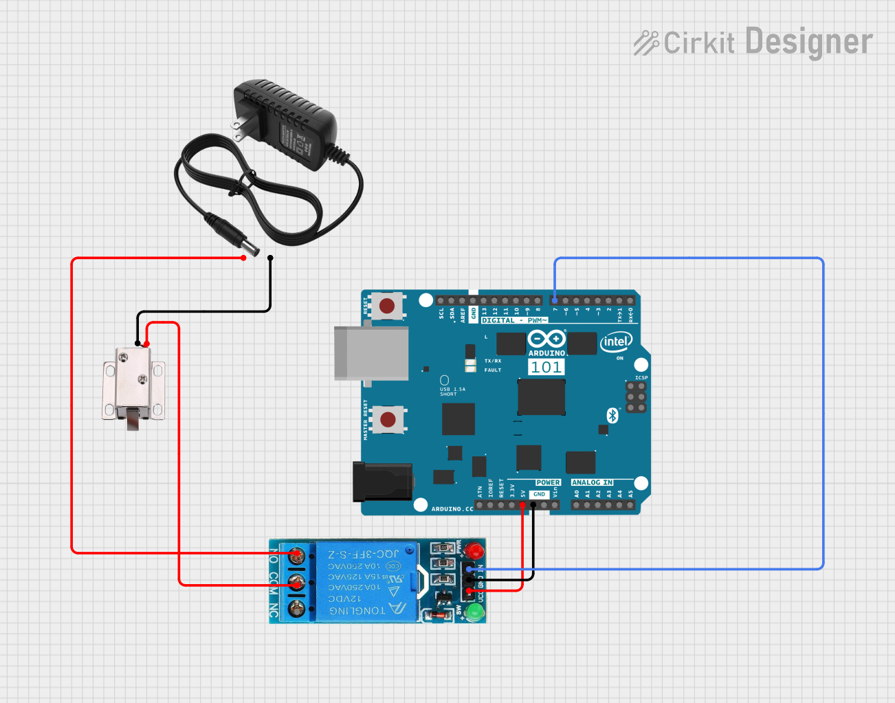
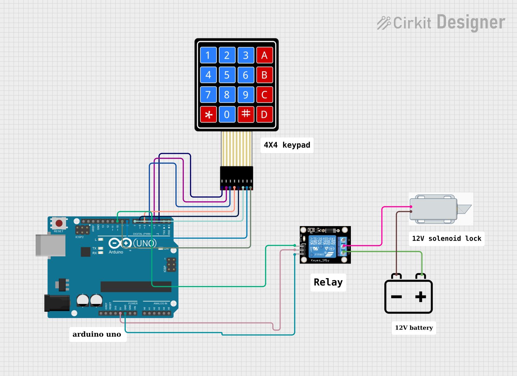
Below is an example of how to control a 12V solenoid lock using an Arduino UNO and a relay module:
Circuit Diagram
- Connect the solenoid lock's red wire to the relay's NO (Normally Open) terminal.
- Connect the solenoid lock's black wire to the ground.
- Connect the relay's COM (Common) terminal to the 12V DC power supply.
- Connect the relay's control pin to an Arduino digital pin (e.g., pin 7).
Arduino Code
// Example code to control a 12V solenoid lock using an Arduino UNO
// and a relay module. The solenoid lock will activate for 2 seconds
// when the Arduino sends a HIGH signal to the relay.

const int relayPin = 7; // Define the pin connected to the relay module

void setup() {
  pinMode(relayPin, OUTPUT); // Set the relay pin as an output
  digitalWrite(relayPin, LOW); // Ensure the relay is off initially
}

void loop() {
  digitalWrite(relayPin, HIGH); // Activate the relay (lock opens)
  delay(2000); // Keep the lock open for 2 seconds
  digitalWrite(relayPin, LOW); // Deactivate the relay (lock closes)
  delay(5000); // Wait for 5 seconds before repeating
}
Troubleshooting and FAQs
Common Issues and Solutions
The solenoid lock does not activate:
- Cause: Insufficient power supply or incorrect wiring.
- Solution: Verify the power supply provides 12V DC and at least 1A. Check the wiring for proper connections.
The solenoid lock overheats:
- Cause: Prolonged activation or insufficient cooling.
- Solution: Limit activation time to a few seconds. Allow the solenoid to cool between activations.
Voltage spikes damage the circuit:
- Cause: Lack of a flyback diode.
- Solution: Install a flyback diode (e.g., 1N4007) across the solenoid terminals.
The lock remains open or closed unexpectedly:
- Cause: Faulty relay or incorrect control signal.
- Solution: Test the relay module and ensure the control signal from the microcontroller is correct.
FAQs
Q: Can I use a 9V battery to power the solenoid lock?
A: No, a 9V battery cannot provide sufficient voltage or current to operate the solenoid lock reliably. Use a 12V DC power supply.
Q: Is the solenoid lock waterproof?
A: Most solenoid locks are not waterproof. Check the manufacturer's specifications for water resistance, or use the lock in a protected environment.
Q: Can I control the solenoid lock directly with an Arduino?
A: No, the Arduino cannot supply the required current. Use a relay module, transistor, or MOSFET to control the solenoid lock.
Q: What happens if I reverse the polarity of the wires?
A: Reversing the polarity may damage the solenoid lock. Always connect the red wire to +12V and the black wire to ground.