How to Use MLX90614: Examples, Pinouts, and Specs
Introduction
The MLX90614 is a non-contact infrared thermometer designed to measure the temperature of objects without requiring direct physical contact. It operates by detecting infrared radiation emitted by objects and converting it into a temperature reading. This sensor is highly versatile and is widely used in applications such as medical thermometers, industrial temperature monitoring, HVAC systems, and automotive climate control.
The MLX90614 is particularly valued for its accuracy, ease of use, and ability to measure both object and ambient temperatures. Its digital interface makes it compatible with microcontrollers like Arduino, Raspberry Pi, and other embedded systems.
Explore Projects Built with MLX90614
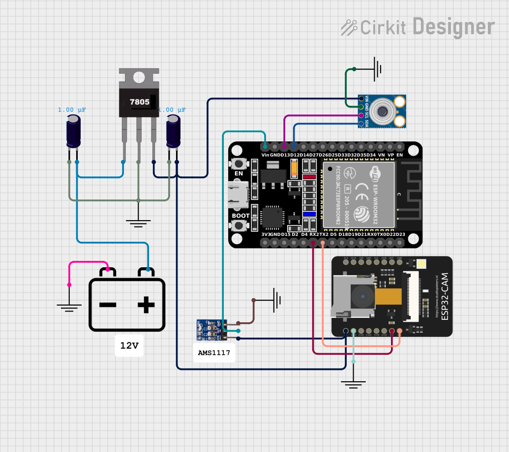
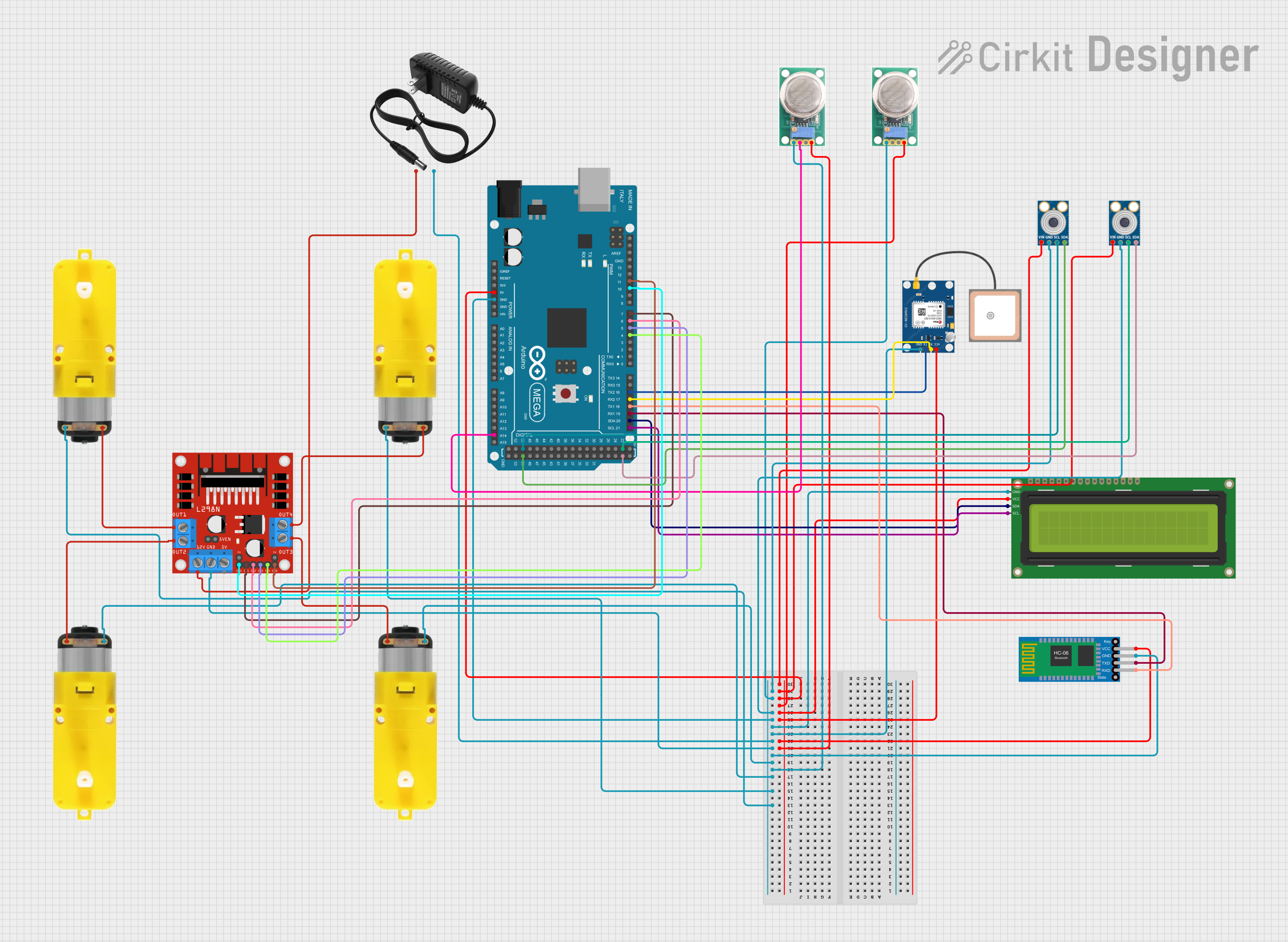

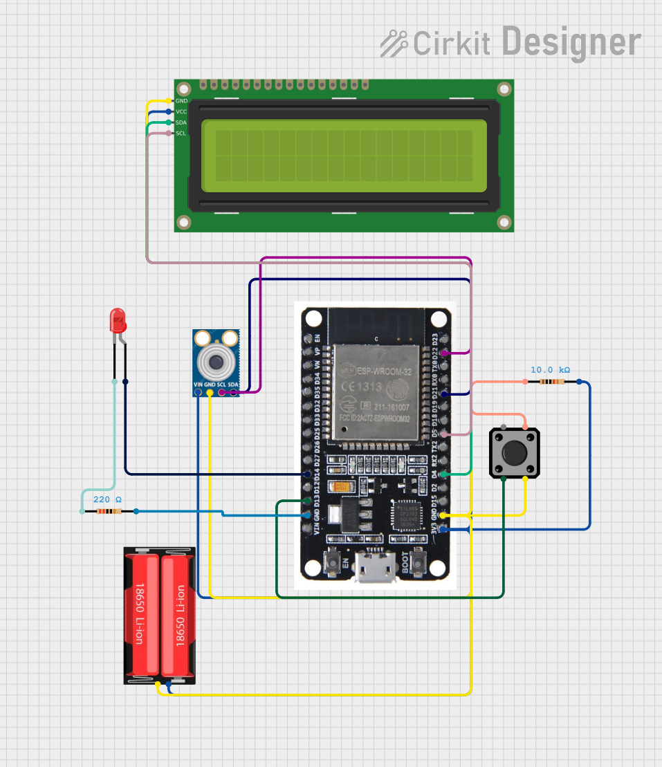
Explore Projects Built with MLX90614
Technical Specifications
The MLX90614 is available in various models, but the following are the general technical specifications for the most commonly used version:
| Parameter | Value |
|---|---|
| Operating Voltage | 3.6V to 5V |
| Current Consumption | 1.5mA (typical) |
| Temperature Range (Object) | -70°C to +380°C |
| Temperature Range (Ambient) | -40°C to +125°C |
| Accuracy | ±0.5°C (typical, for 0°C to +50°C range) |
| Field of View (FOV) | 35° |
| Communication Protocol | I²C and PWM |
| Resolution | 0.02°C |
Pin Configuration and Descriptions
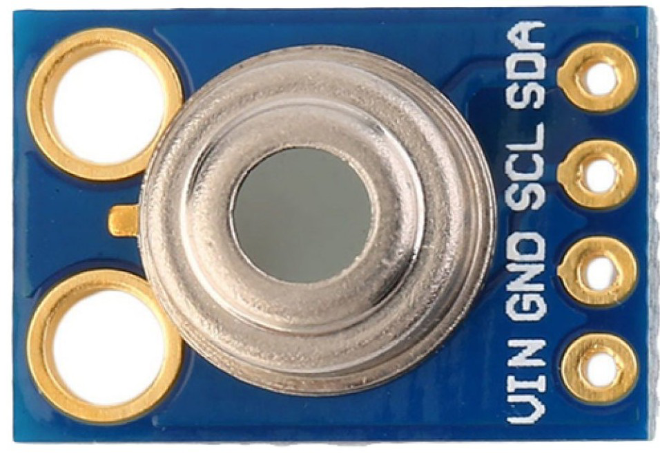
The MLX90614 typically comes in a 4-pin TO-39 package. Below is the pin configuration:
| Pin | Name | Description |
|---|---|---|
| 1 | VDD | Power supply (3.6V to 5V) |
| 2 | VSS | Ground |
| 3 | SDA | Serial Data Line for I²C communication |
| 4 | SCL | Serial Clock Line for I²C communication |
Usage Instructions
How to Use the MLX90614 in a Circuit
- Power Supply: Connect the VDD pin to a 3.6V to 5V power source and the VSS pin to ground.
- I²C Communication: Use the SDA and SCL pins to interface with a microcontroller. Pull-up resistors (typically 4.7kΩ) are required on both SDA and SCL lines for proper I²C operation.
- Object Placement: Ensure the object to be measured is within the sensor's field of view (35° cone). Avoid obstructions or reflective surfaces that may interfere with accurate readings.
Important Considerations and Best Practices
- Ambient Temperature: The sensor's accuracy is optimal when the ambient temperature is within its specified range (-40°C to +125°C).
- Field of View: Ensure the object being measured occupies the majority of the sensor's field of view to avoid averaging errors.
- Power Supply Noise: Use a decoupling capacitor (e.g., 0.1µF) near the VDD pin to minimize noise and ensure stable operation.
- Avoid Direct Sunlight: Prolonged exposure to direct sunlight can affect the sensor's accuracy and longevity.
Example: Using MLX90614 with Arduino UNO
Below is an example of how to interface the MLX90614 with an Arduino UNO using the I²C protocol. This example uses the Adafruit MLX90614 library.
Circuit Connections
- Connect the MLX90614's VDD to the Arduino's 5V pin.
- Connect the MLX90614's VSS to the Arduino's GND pin.
- Connect the SDA pin to the Arduino's A4 pin (I²C data line).
- Connect the SCL pin to the Arduino's A5 pin (I²C clock line).
Arduino Code
#include <Wire.h>
#include <Adafruit_MLX90614.h>

// Create an instance of the MLX90614 library
Adafruit_MLX90614 mlx = Adafruit_MLX90614();

void setup() {
  Serial.begin(9600); // Initialize serial communication at 9600 baud
  Serial.println("MLX90614 Test");

  if (!mlx.begin()) {
    Serial.println("Error: Could not find a valid MLX90614 sensor!");
    while (1); // Halt execution if sensor initialization fails
  }
}

void loop() {
  // Read object temperature in Celsius
  double objectTemp = mlx.readObjectTempC();
  // Read ambient temperature in Celsius
  double ambientTemp = mlx.readAmbientTempC();

  // Print the temperatures to the Serial Monitor
  Serial.print("Object Temperature: ");
  Serial.print(objectTemp);
  Serial.println(" °C");

  Serial.print("Ambient Temperature: ");
  Serial.print(ambientTemp);
  Serial.println(" °C");

  delay(1000); // Wait for 1 second before the next reading
}
Troubleshooting and FAQs
Common Issues and Solutions
No Data or Incorrect Readings:
- Ensure proper pull-up resistors (4.7kΩ) are connected to the SDA and SCL lines.
- Verify that the sensor is powered correctly (3.6V to 5V).
- Check the I²C address of the sensor. The default address is
0x5A.
Inconsistent Temperature Readings:
- Ensure the object being measured is within the sensor's field of view.
- Avoid measuring reflective or shiny surfaces directly, as they can distort readings.
Sensor Not Detected:
- Confirm that the SDA and SCL lines are connected to the correct pins on the microcontroller.
- Check for loose or faulty wiring.
FAQs
Q1: Can the MLX90614 measure human body temperature?
Yes, the MLX90614 is commonly used in medical thermometers to measure human body temperature. Ensure the sensor is calibrated for the specific application.
Q2: Can I use the MLX90614 with a 3.3V microcontroller?
Yes, the MLX90614 can operate at 3.6V, which is compatible with 3.3V systems. However, ensure proper level shifting for I²C communication if needed.
Q3: How do I reduce noise in the temperature readings?
Use a decoupling capacitor (e.g., 0.1µF) near the VDD pin and ensure the sensor is not exposed to electrical or thermal noise sources.
Q4: What is the maximum distance for accurate temperature measurement?
The effective distance depends on the size of the object and its ability to fill the sensor's field of view. For small objects, the sensor should be placed closer for accurate readings.
This concludes the documentation for the MLX90614.