How to Use Rhino DC Servo Driver: Examples, Pinouts, and Specs
Introduction
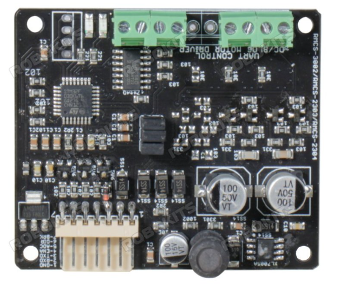
The Rhino DC Servo Driver (RMCS-2303) is a high-performance electronic device designed to control DC servo motors with precision. It regulates the voltage and current supplied to the motor, enabling accurate control of speed, position, and torque. This driver is ideal for applications requiring precise motion control, such as robotics, CNC machines, automated systems, and industrial equipment.
Explore Projects Built with Rhino DC Servo Driver
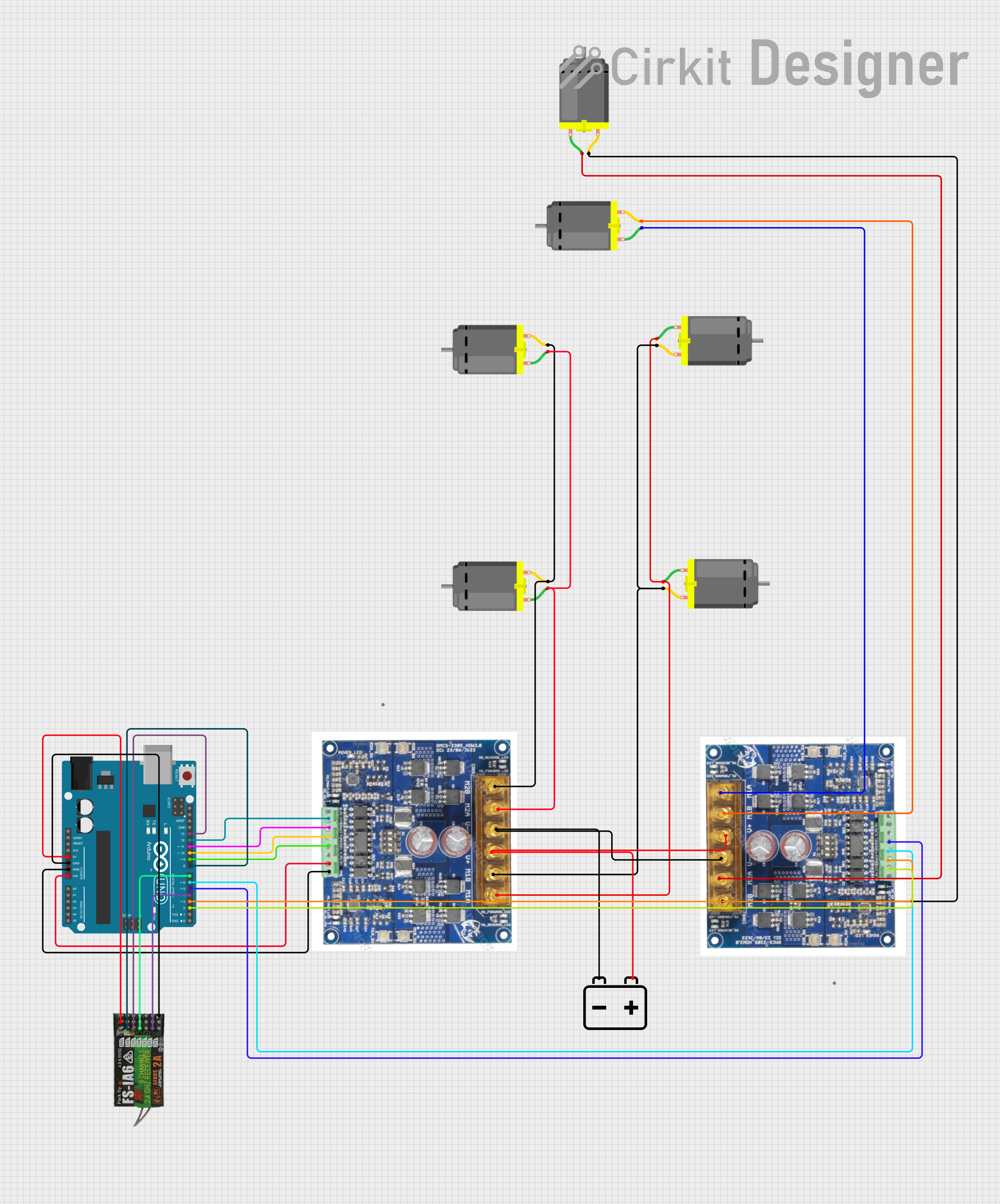

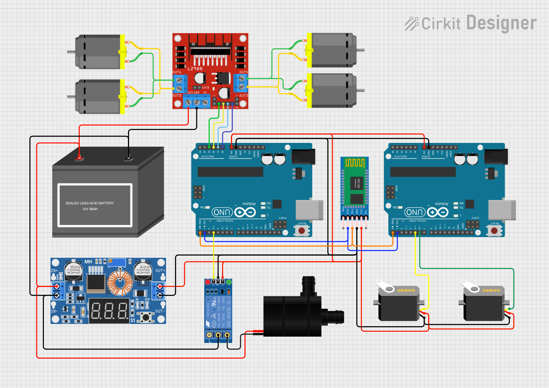
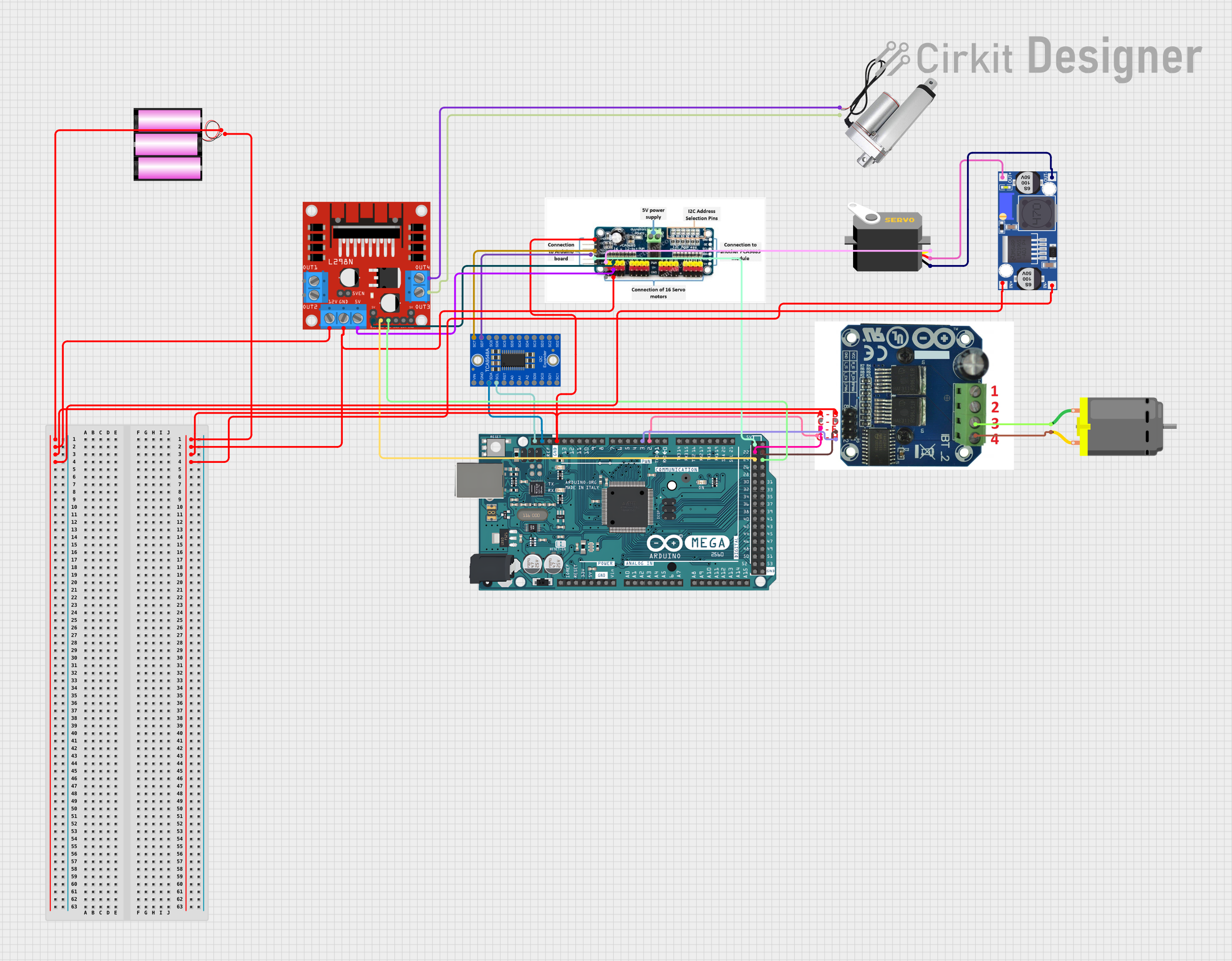
Explore Projects Built with Rhino DC Servo Driver
Common Applications
- Robotics and automation systems
- CNC machines and 3D printers
- Conveyor belts and industrial machinery
- Camera gimbals and pan-tilt systems
- Precision positioning systems
Technical Specifications
Key Technical Details
| Parameter | Specification |
|---|---|
| Manufacturer | Rhino |
| Part ID | RMCS-2303 |
| Input Voltage Range | 12V to 36V DC |
| Continuous Current | Up to 3A |
| Peak Current | 6A (for short durations) |
| Control Signal Input | PWM, Analog (0-5V), or UART |
| Motor Type Supported | DC Servo Motors |
| Feedback Type | Encoder (Quadrature) |
| Operating Temperature | -10°C to 50°C |
| Dimensions | 75mm x 50mm x 20mm |
| Weight | 100g |
Pin Configuration and Descriptions
The RMCS-2303 features a set of input/output pins for motor control, feedback, and power connections. Below is the pin configuration:
Power and Motor Connections
| Pin Number | Pin Name | Description |
|---|---|---|
| 1 | V+ | Positive power supply input (12V to 36V DC) |
| 2 | GND | Ground connection for power supply |
| 3 | M+ | Positive terminal of the DC motor |
| 4 | M- | Negative terminal of the DC motor |
Control Signal Inputs
| Pin Number | Pin Name | Description |
|---|---|---|
| 5 | PWM | PWM signal input for speed control |
| 6 | DIR | Direction control input (High/Low) |
| 7 | EN | Enable input (High to enable the driver) |
| 8 | ANLG | Analog input for speed control (0-5V) |
Feedback Connections
| Pin Number | Pin Name | Description |
|---|---|---|
| 9 | ENC_A | Encoder channel A input |
| 10 | ENC_B | Encoder channel B input |
| 11 | ENC_VCC | Encoder power supply (5V output) |
| 12 | ENC_GND | Encoder ground connection |
Usage Instructions
How to Use the RMCS-2303 in a Circuit
- Power Supply: Connect a DC power supply (12V to 36V) to the
V+andGNDpins. Ensure the power supply can provide sufficient current for the motor. - Motor Connection: Connect the DC servo motor to the
M+andM-pins. - Control Signal:
- For PWM control, connect a PWM signal to the
PWMpin and set the desired duty cycle. - Use the
DIRpin to control the motor's direction (High for forward, Low for reverse). - Optionally, use the
ANLGpin for analog speed control (0-5V input).
- For PWM control, connect a PWM signal to the
- Feedback: Connect the motor's encoder outputs to the
ENC_AandENC_Bpins for position feedback. Provide power to the encoder using theENC_VCCandENC_GNDpins. - Enable the Driver: Set the
ENpin to High to enable the driver.
Important Considerations
- Ensure the power supply voltage matches the motor's operating range.
- Use appropriate heat dissipation methods if the driver operates at high currents for extended periods.
- Verify the encoder wiring and signal compatibility with the driver.
- Avoid reversing the polarity of the power supply or motor connections.
Example: Using RMCS-2303 with Arduino UNO
Below is an example of controlling the RMCS-2303 using an Arduino UNO with PWM and direction control:
// Define pin connections
const int pwmPin = 9;  // PWM signal pin
const int dirPin = 8;  // Direction control pin
const int enPin = 7;   // Enable pin

void setup() {
  // Set pin modes
  pinMode(pwmPin, OUTPUT);
  pinMode(dirPin, OUTPUT);
  pinMode(enPin, OUTPUT);

  // Enable the driver
  digitalWrite(enPin, HIGH);
}

void loop() {
  // Set motor direction to forward
  digitalWrite(dirPin, HIGH);

  // Set motor speed using PWM (50% duty cycle)
  analogWrite(pwmPin, 128);

  delay(2000); // Run motor for 2 seconds

  // Set motor direction to reverse
  digitalWrite(dirPin, LOW);

  // Set motor speed using PWM (75% duty cycle)
  analogWrite(pwmPin, 192);

  delay(2000); // Run motor for 2 seconds
}
Troubleshooting and FAQs
Common Issues and Solutions
Motor Not Running:
- Ensure the
ENpin is set to High. - Verify the power supply voltage and current ratings.
- Check the motor connections (
M+andM-).
- Ensure the
Erratic Motor Behavior:
- Verify the encoder connections (
ENC_AandENC_B). - Ensure the control signals (PWM, DIR) are stable and within the specified range.
- Verify the encoder connections (
Overheating:
- Check for excessive current draw from the motor.
- Use a heatsink or cooling fan if necessary.
No Feedback from Encoder:
- Confirm the encoder wiring and power supply (
ENC_VCCandENC_GND). - Check the encoder's compatibility with the RMCS-2303.
- Confirm the encoder wiring and power supply (
FAQs
Q: Can I use the RMCS-2303 with a battery-powered system?
A: Yes, as long as the battery voltage is within the 12V to 36V range and can supply sufficient current.
Q: What type of motors are compatible with the RMCS-2303?
A: The RMCS-2303 is designed for DC servo motors with encoder feedback.
Q: Can I control the RMCS-2303 using UART?
A: Yes, the RMCS-2303 supports UART communication for advanced control. Refer to the manufacturer's UART protocol documentation for details.
Q: Is the RMCS-2303 protected against reverse polarity?
A: No, ensure correct polarity when connecting the power supply to avoid damage.
This concludes the documentation for the Rhino DC Servo Driver (RMCS-2303). For further assistance, refer to the manufacturer's user manual or contact technical support.