How to Use ADE7753: Examples, Pinouts, and Specs
ADE7753 Energy Metering IC Documentation
Introduction
The ADE7753 is a high-accuracy energy metering integrated circuit (IC) designed for single-phase energy measurement applications. Manufactured by Analog Devices, this IC is capable of measuring both active and reactive energy with exceptional precision. It integrates an analog-to-digital converter (ADC), a digital signal processor (DSP), and supports SPI communication for seamless data transmission. The ADE7753 is widely used in energy meters, power monitoring systems, and industrial automation.
Common Applications
- Single-phase energy meters
- Power monitoring and management systems
- Industrial automation and control
- Smart home energy monitoring
- Renewable energy systems (e.g., solar inverters)
Technical Specifications
The following table outlines the key technical specifications of the ADE7753:
| Parameter | Value |
|---|---|
| Supply Voltage (VDD) | 4.75V to 5.25V |
| Power Consumption | < 25mW |
| Input Voltage Range | ±0.5V (differential inputs) |
| ADC Resolution | 16-bit |
| Measurement Accuracy | 0.1% error over 1000:1 dynamic range |
| Communication Interface | SPI |
| Operating Temperature Range | -40°C to +85°C |
| Package Type | 20-lead SSOP |
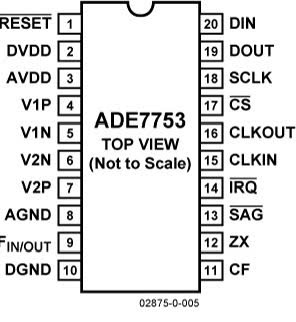
Pin Configuration and Descriptions
The ADE7753 comes in a 20-lead SSOP package. Below is the pin configuration and description:
| Pin No. | Pin Name | Description |
|---|---|---|
| 1 | VDD | Positive power supply (4.75V to 5.25V). |
| 2 | AGND | Analog ground. |
| 3 | V1P | Positive input for voltage channel 1. |
| 4 | V1N | Negative input for voltage channel 1. |
| 5 | V2P | Positive input for voltage channel 2. |
| 6 | V2N | Negative input for voltage channel 2. |
| 7 | REVP | Reverse power indication output. |
| 8 | IRQ | Interrupt request output. |
| 9 | SCLK | SPI clock input. |
| 10 | SDI | SPI data input. |
| 11 | SDO | SPI data output. |
| 12 | CS | SPI chip select input. |
| 13 | RESET | Reset input (active low). |
| 14 | CLKIN | External clock input. |
| 15 | CLKOUT | Clock output. |
| 16 | DGND | Digital ground. |
| 17 | CF | Calibration frequency output. |
| 18 | ZX | Zero-crossing detection output. |
| 19 | F1 | Frequency output 1 for energy pulse. |
| 20 | F2 | Frequency output 2 for energy pulse. |
Usage Instructions
How to Use the ADE7753 in a Circuit
Power Supply:
- Connect the VDD pin to a regulated 5V power supply.
- Connect the AGND and DGND pins to the ground plane of the circuit.
Voltage and Current Inputs:
- Use appropriate voltage dividers and current transformers to scale the input signals to the IC's input range (±0.5V).
- Connect the scaled voltage signals to V1P/V1N and current signals to V2P/V2N.
SPI Communication:
- Connect the SCLK, SDI, SDO, and CS pins to the SPI interface of a microcontroller (e.g., Arduino UNO).
- Ensure proper pull-up resistors are used if required.
Clock Configuration:
- Provide an external clock signal to the CLKIN pin or use an external crystal oscillator.
Interrupts and Outputs:
- Use the IRQ pin to handle interrupts for events like zero-crossing or energy thresholds.
- The CF, F1, and F2 pins can be used to output energy pulses for calibration or monitoring.
Best Practices
- Use decoupling capacitors (e.g., 0.1µF) close to the power supply pins to reduce noise.
- Ensure proper isolation between high-voltage and low-voltage sections of the circuit.
- Calibrate the IC using the CF output to ensure accurate energy measurements.
Interfacing with Arduino UNO
The ADE7753 can be interfaced with an Arduino UNO via the SPI interface. Below is an example code snippet to read data from the ADE7753:
#include <SPI.h>

// Define SPI pins for ADE7753
const int CS_PIN = 10; // Chip Select pin for ADE7753

void setup() {
  // Initialize Serial Monitor
  Serial.begin(9600);

  // Configure SPI settings
  SPI.begin();
  SPI.setDataMode(SPI_MODE1); // ADE7753 uses SPI Mode 1
  SPI.setClockDivider(SPI_CLOCK_DIV16); // Set SPI clock speed
  pinMode(CS_PIN, OUTPUT);
  digitalWrite(CS_PIN, HIGH); // Set CS pin high (inactive)
}

uint8_t readRegister(uint8_t regAddress) {
  digitalWrite(CS_PIN, LOW); // Select ADE7753
  SPI.transfer(regAddress | 0x80); // Send register address with read bit
  uint8_t data = SPI.transfer(0x00); // Read data from register
  digitalWrite(CS_PIN, HIGH); // Deselect ADE7753
  return data;
}

void loop() {
  // Example: Read the status register (address 0x0A)
  uint8_t status = readRegister(0x0A);
  Serial.print("Status Register: 0x");
  Serial.println(status, HEX);

  delay(1000); // Wait 1 second before next read
}
Troubleshooting and FAQs
Common Issues and Solutions
No Communication via SPI:
- Ensure the SPI pins (SCLK, SDI, SDO, CS) are correctly connected.
- Verify that the SPI mode is set to Mode 1 in the microcontroller.
Incorrect Energy Measurements:
- Check the input signal scaling (voltage dividers and current transformers).
- Calibrate the IC using the CF output.
High Noise in Measurements:
- Use proper grounding and shielding techniques.
- Add decoupling capacitors near the IC.
Interrupts Not Triggering:
- Verify the configuration of the IRQ pin and ensure it is connected to the microcontroller.
FAQs
Q1: Can the ADE7753 measure power factor?
A1: Yes, the ADE7753 can measure power factor indirectly by calculating the phase difference between voltage and current inputs.
Q2: What is the maximum sampling rate of the ADC?
A2: The ADC in the ADE7753 operates at a maximum sampling rate of 16kHz.
Q3: Is the ADE7753 suitable for three-phase systems?
A3: No, the ADE7753 is designed specifically for single-phase energy measurement applications.
This documentation provides a comprehensive guide to using the ADE7753 energy metering IC. For further details, refer to the official datasheet provided by Analog Devices.
Explore Projects Built with ADE7753


Explore Projects Built with ADE7753