Cirkit Designer Logo
Cirkit Designer
Your all-in-one circuit design IDE
Home / 
Component Documentation

How to Use Peristaltic Pump Kamoer 12V: Examples, Pinouts, and Specs
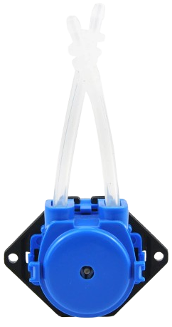

Image of Peristaltic Pump Kamoer 12V
Cirkit Designer LogoDesign with Peristaltic Pump Kamoer 12V in Cirkit Designer

Introduction

The Peristaltic Pump Kamoer 12V is a compact and efficient pump designed for precise fluid transfer. It operates using a series of rollers that compress a flexible tube, enabling accurate and contamination-free liquid movement. This pump is powered by a 12V DC supply, making it versatile and easy to integrate into various systems. Its design ensures minimal maintenance and high reliability, making it ideal for applications in laboratories, aquariums, medical devices, and other fluid-handling systems.

Explore Projects Built with Peristaltic Pump Kamoer 12V
Use Cirkit Designer to design, explore, and prototype these projects online. Some projects support real-time simulation. Click "Open Project" to start designing instantly!
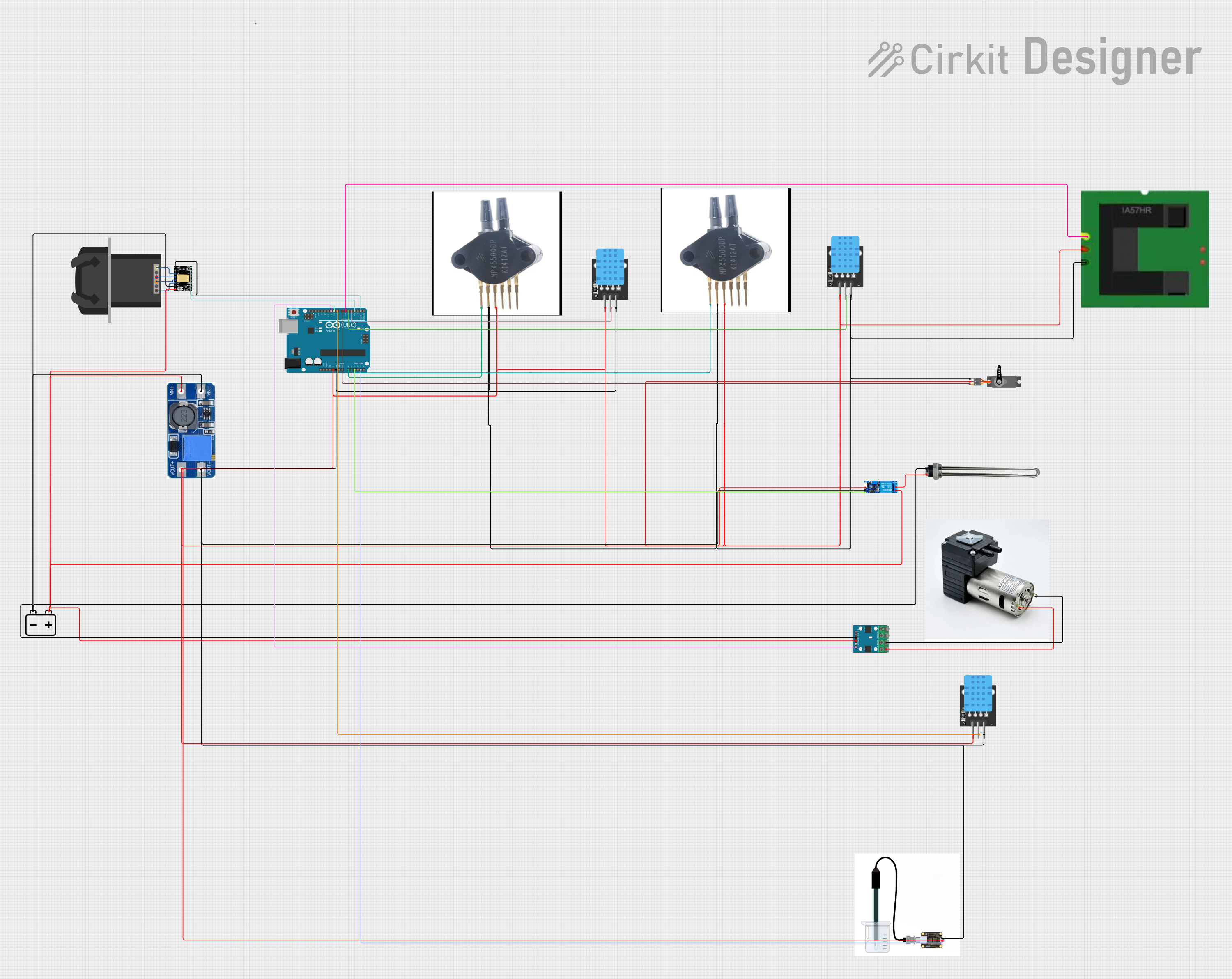
Arduino UNO Controlled Peristaltic Pump System with Temperature and Pressure Monitoring
Image of blood circit: A project utilizing Peristaltic Pump Kamoer 12V in a practical application
This circuit is designed to control a KPCS200 peristaltic pump using a TMC2226 stepper driver, powered by a 12V battery and regulated by a step-up boost converter. An Arduino UNO microcontroller manages various sensors, including temperature, pressure, and conductivity sensors, as well as a servo and a relay module for a water heater, enabling precise control and monitoring of fluid flow and environmental conditions.
Cirkit Designer LogoOpen Project in Cirkit Designer
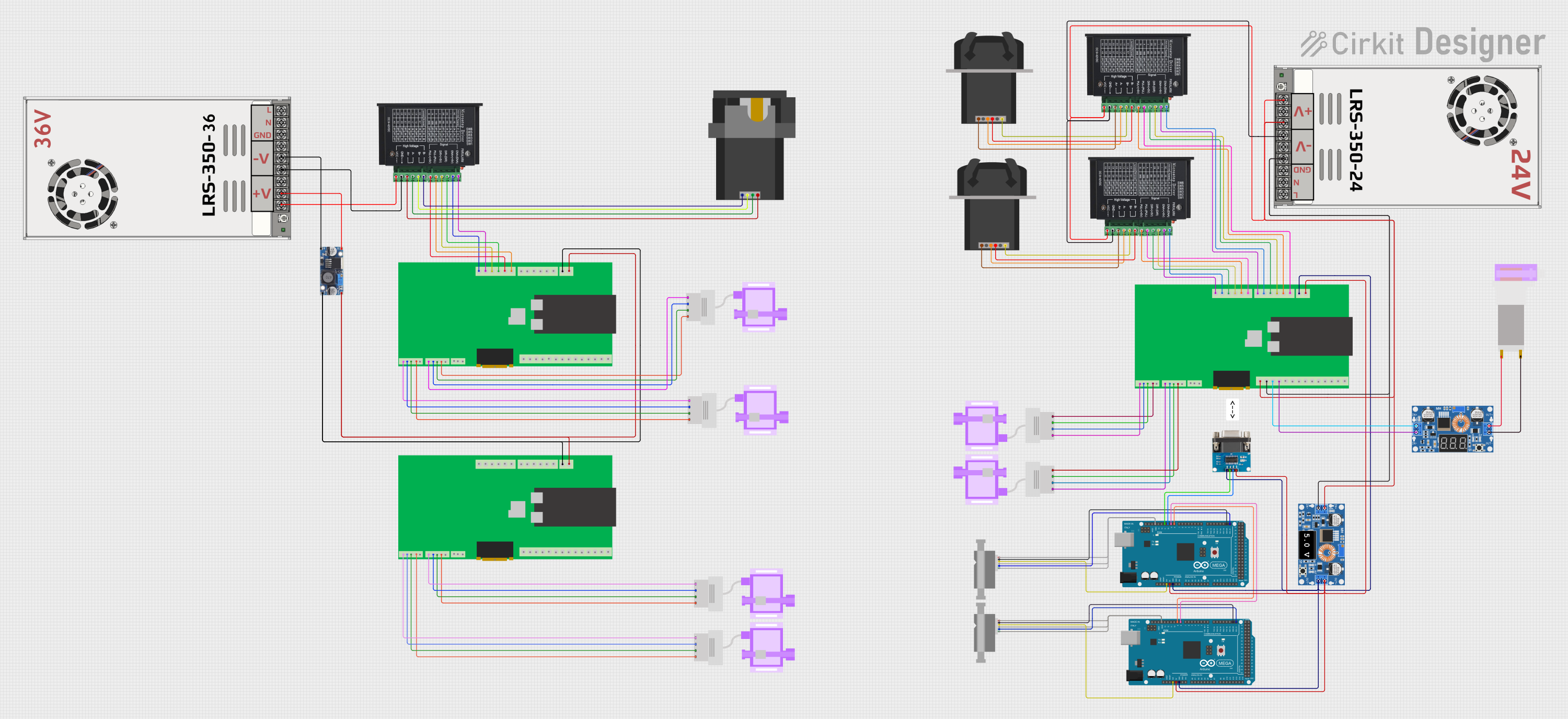
Automated Peristaltic Pump Control System with Arduino and ESP32
Image of Long-Term Bench: A project utilizing Peristaltic Pump Kamoer 12V in a practical application
This circuit appears to be a control system for peristaltic pumps and a motor driver, with power regulation and communication capabilities. It includes a main power supply stepping down from 48V to various lower voltages for different components, two tb6600 micro stepping motor drivers controlling peristaltic pumps, and an ESP32-based custom PCB for managing signals and communication. The system also integrates an Arduino Mega for additional control and interfacing with a Sensirion flow meter, RS232 to TTL converters for serial communication, and an ultrasonic sensor for distance measurement.
Cirkit Designer LogoOpen Project in Cirkit Designer
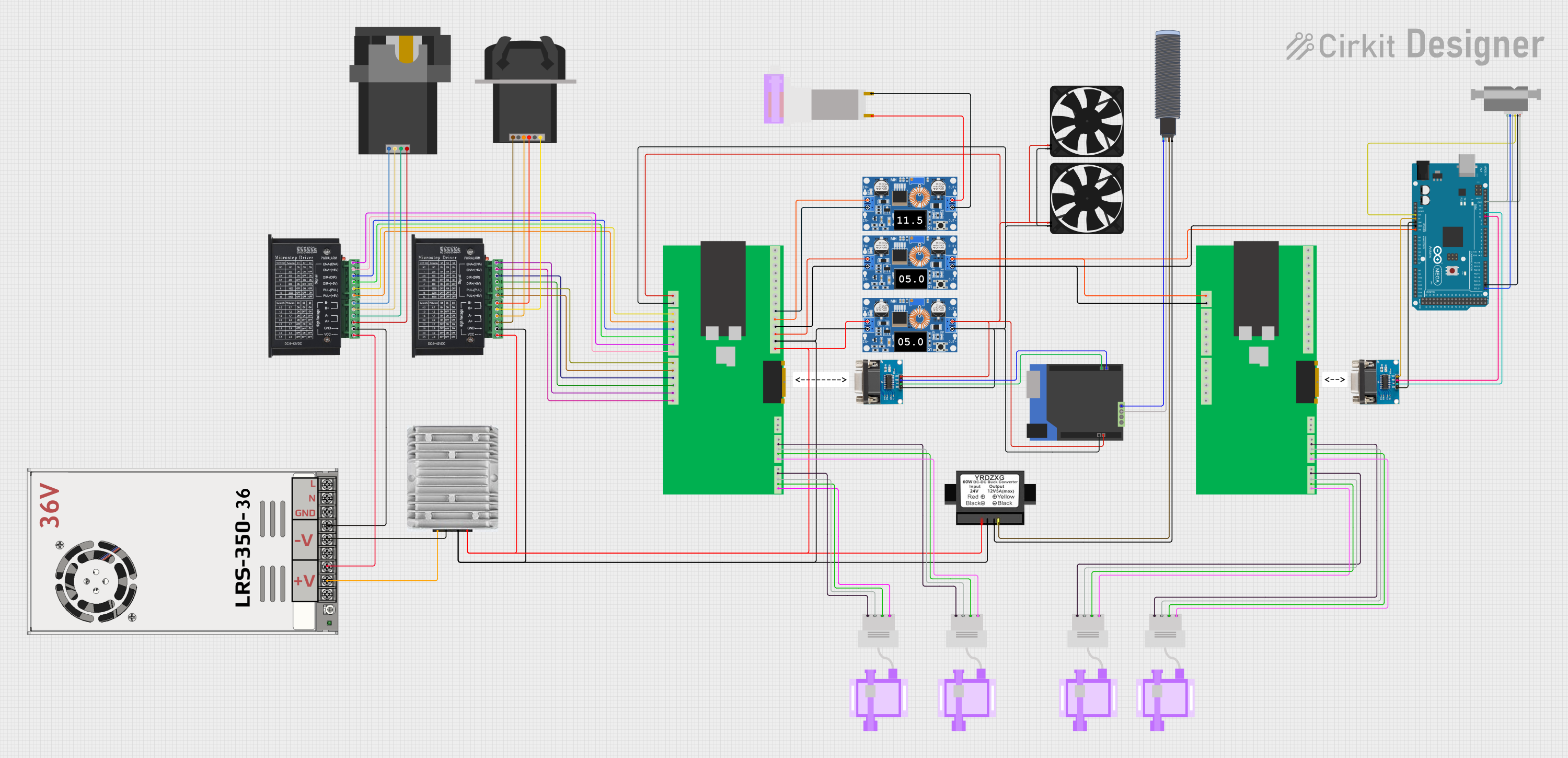
ESP32 and Arduino Mega 2560 Controlled Peristaltic Pump System with Pressure and Flow Sensors
Image of Blood & Dialysate Control Bench: A project utilizing Peristaltic Pump Kamoer 12V in a practical application
This circuit is designed for fluid control and monitoring, featuring multiple peristaltic pumps driven by TB6600 micro-stepping motor drivers, and pressure sensors interfaced with custom PCBs containing ESP32 microcontrollers. It also includes flow meters connected to Arduino Mega 2560 boards for precise flow rate measurement, with power management handled by DC-DC converters and power supplies.
Cirkit Designer LogoOpen Project in Cirkit Designer
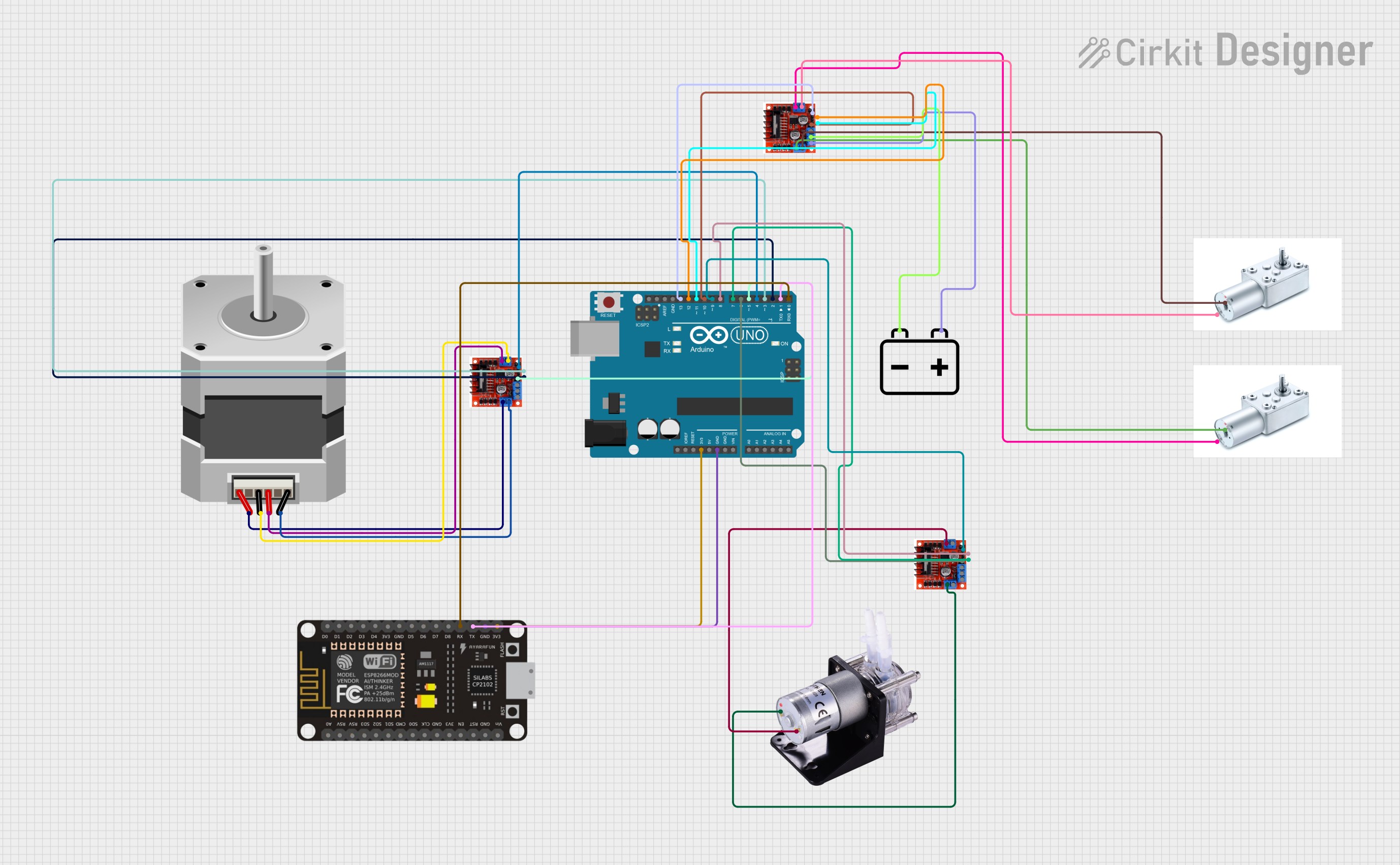
Arduino and ESP-8266 Controlled Peristaltic Pump and Stepper Motor System with L298N Motor Drivers
Image of Group 5 Circuit : A project utilizing Peristaltic Pump Kamoer 12V in a practical application
This circuit controls a peristaltic pump and two types of motors (a NEMA23 stepper motor and two Greartisan DC geared motors) using an Arduino UNO and an ESP-8266 for potential wireless communication. The Arduino UNO interfaces with three L298N motor driver modules to drive the motors, and it is also connected to the ESP-8266, which may be used for remote signaling or data transmission. The circuit is powered by a 12V battery, which supplies power to the motor drivers and, through them, to the motors and the pump.
Cirkit Designer LogoOpen Project in Cirkit Designer

Explore Projects Built with Peristaltic Pump Kamoer 12V

Use Cirkit Designer to design, explore, and prototype these projects online. Some projects support real-time simulation. Click "Open Project" to start designing instantly!
Image of blood circit: A project utilizing Peristaltic Pump Kamoer 12V in a practical application
Arduino UNO Controlled Peristaltic Pump System with Temperature and Pressure Monitoring
This circuit is designed to control a KPCS200 peristaltic pump using a TMC2226 stepper driver, powered by a 12V battery and regulated by a step-up boost converter. An Arduino UNO microcontroller manages various sensors, including temperature, pressure, and conductivity sensors, as well as a servo and a relay module for a water heater, enabling precise control and monitoring of fluid flow and environmental conditions.
Cirkit Designer LogoOpen Project in Cirkit Designer
Image of Long-Term Bench: A project utilizing Peristaltic Pump Kamoer 12V in a practical application
Automated Peristaltic Pump Control System with Arduino and ESP32
This circuit appears to be a control system for peristaltic pumps and a motor driver, with power regulation and communication capabilities. It includes a main power supply stepping down from 48V to various lower voltages for different components, two tb6600 micro stepping motor drivers controlling peristaltic pumps, and an ESP32-based custom PCB for managing signals and communication. The system also integrates an Arduino Mega for additional control and interfacing with a Sensirion flow meter, RS232 to TTL converters for serial communication, and an ultrasonic sensor for distance measurement.
Cirkit Designer LogoOpen Project in Cirkit Designer
Image of Blood & Dialysate Control Bench: A project utilizing Peristaltic Pump Kamoer 12V in a practical application
ESP32 and Arduino Mega 2560 Controlled Peristaltic Pump System with Pressure and Flow Sensors
This circuit is designed for fluid control and monitoring, featuring multiple peristaltic pumps driven by TB6600 micro-stepping motor drivers, and pressure sensors interfaced with custom PCBs containing ESP32 microcontrollers. It also includes flow meters connected to Arduino Mega 2560 boards for precise flow rate measurement, with power management handled by DC-DC converters and power supplies.
Cirkit Designer LogoOpen Project in Cirkit Designer
Image of Group 5 Circuit : A project utilizing Peristaltic Pump Kamoer 12V in a practical application
Arduino and ESP-8266 Controlled Peristaltic Pump and Stepper Motor System with L298N Motor Drivers
This circuit controls a peristaltic pump and two types of motors (a NEMA23 stepper motor and two Greartisan DC geared motors) using an Arduino UNO and an ESP-8266 for potential wireless communication. The Arduino UNO interfaces with three L298N motor driver modules to drive the motors, and it is also connected to the ESP-8266, which may be used for remote signaling or data transmission. The circuit is powered by a 12V battery, which supplies power to the motor drivers and, through them, to the motors and the pump.
Cirkit Designer LogoOpen Project in Cirkit Designer

Common Applications:

  • Laboratory fluid dosing and sampling
  • Aquarium water treatment and nutrient dosing
  • Medical devices requiring sterile fluid transfer
  • Industrial chemical handling and dispensing
  • Food and beverage processing

Technical Specifications

Key Technical Details:

Parameter Specification
Operating Voltage 12V DC
Current Consumption ~200mA (varies with load)
Flow Rate 0-100 mL/min (adjustable)
Tube Material Silicone or compatible material
Tube Inner Diameter 2-3 mm
Roller Mechanism 3-roller system
Lifespan ~1000 hours (tube-dependent)
Dimensions 79 x 49 x 45 mm
Weight ~150g

Pin Configuration and Descriptions:

Pin/Connection Description
V+ Positive terminal for 12V DC input
GND Ground terminal for power supply
Signal (optional) PWM input for speed control (if supported)

Usage Instructions

How to Use the Peristaltic Pump in a Circuit:

  1. Power Supply: Connect the V+ pin to a 12V DC power source and the GND pin to the ground of the same power source.
  2. Fluid Tubing: Insert the flexible silicone tube into the pump's roller mechanism. Ensure the tube is securely seated to prevent leaks or slippage.
  3. Flow Direction: Verify the pump's flow direction by briefly powering it on. Reverse the polarity of the power supply if the flow direction needs to be changed.
  4. Speed Control (Optional): If the pump supports PWM (Pulse Width Modulation) control, connect the signal pin to a PWM-capable microcontroller (e.g., Arduino) to adjust the pump's speed.

Important Considerations:

  • Tube Compatibility: Use tubing that is chemically compatible with the fluid being transferred.
  • Avoid Dry Running: Do not operate the pump without fluid in the tube, as this can cause excessive wear on the tubing.
  • Maintenance: Regularly inspect and replace the tubing to maintain optimal performance and prevent leaks.
  • Polarity Check: Ensure correct polarity when connecting the power supply to avoid damage to the pump.

Example: Controlling the Pump with an Arduino UNO

The following example demonstrates how to control the pump's speed using PWM on an Arduino UNO.

// Define the PWM pin connected to the pump's signal pin
const int pumpPin = 9;

void setup() {
  // Set the pump pin as an output
  pinMode(pumpPin, OUTPUT);
}

void loop() {
  // Gradually increase the pump speed
  for (int speed = 0; speed <= 255; speed += 5) {
    analogWrite(pumpPin, speed); // Write PWM signal to control speed
    delay(100); // Wait for 100ms
  }

  // Gradually decrease the pump speed
  for (int speed = 255; speed >= 0; speed -= 5) {
    analogWrite(pumpPin, speed); // Write PWM signal to control speed
    delay(100); // Wait for 100ms
  }
}

Notes:

  • Ensure the Arduino's ground (GND) is connected to the pump's ground.
  • Use an external power supply for the pump if its current requirements exceed the Arduino's capabilities.

Troubleshooting and FAQs

Common Issues and Solutions:

  1. Pump Not Running:

    • Cause: Incorrect power supply connection.
    • Solution: Verify the polarity and ensure the power supply provides 12V DC.
  2. Low or No Fluid Flow:

    • Cause: Tube not properly seated or damaged.
    • Solution: Check the tube for proper placement and replace it if worn out.
  3. Excessive Noise or Vibration:

    • Cause: Misaligned rollers or worn tubing.
    • Solution: Inspect the roller mechanism and tubing for damage or misalignment.
  4. Inconsistent Flow Rate:

    • Cause: PWM signal instability or tube wear.
    • Solution: Ensure a stable PWM signal and replace the tubing if necessary.

FAQs:

  • Can the pump handle viscous fluids?

    • Yes, but the flow rate may decrease with higher viscosity fluids. Ensure the tubing is compatible with the fluid.
  • Is the pump waterproof?

    • No, the pump is not waterproof. Avoid exposing it to water or other liquids.
  • How often should the tubing be replaced?

    • Tubing lifespan depends on usage and fluid type. Inspect it regularly and replace it when signs of wear or leaks appear.
  • Can the pump run continuously?

    • Yes, but prolonged operation may reduce the tubing's lifespan. Allow periodic rest to extend its durability.