Cirkit Designer Logo
Cirkit Designer
Your all-in-one circuit design IDE
Home / 
Component Documentation

How to Use ESP32 (30 PIN) on Breakout Board: Examples, Pinouts, and Specs

Image of ESP32 (30 PIN) on Breakout Board
Cirkit Designer LogoDesign with ESP32 (30 PIN) on Breakout Board in Cirkit Designer

Introduction

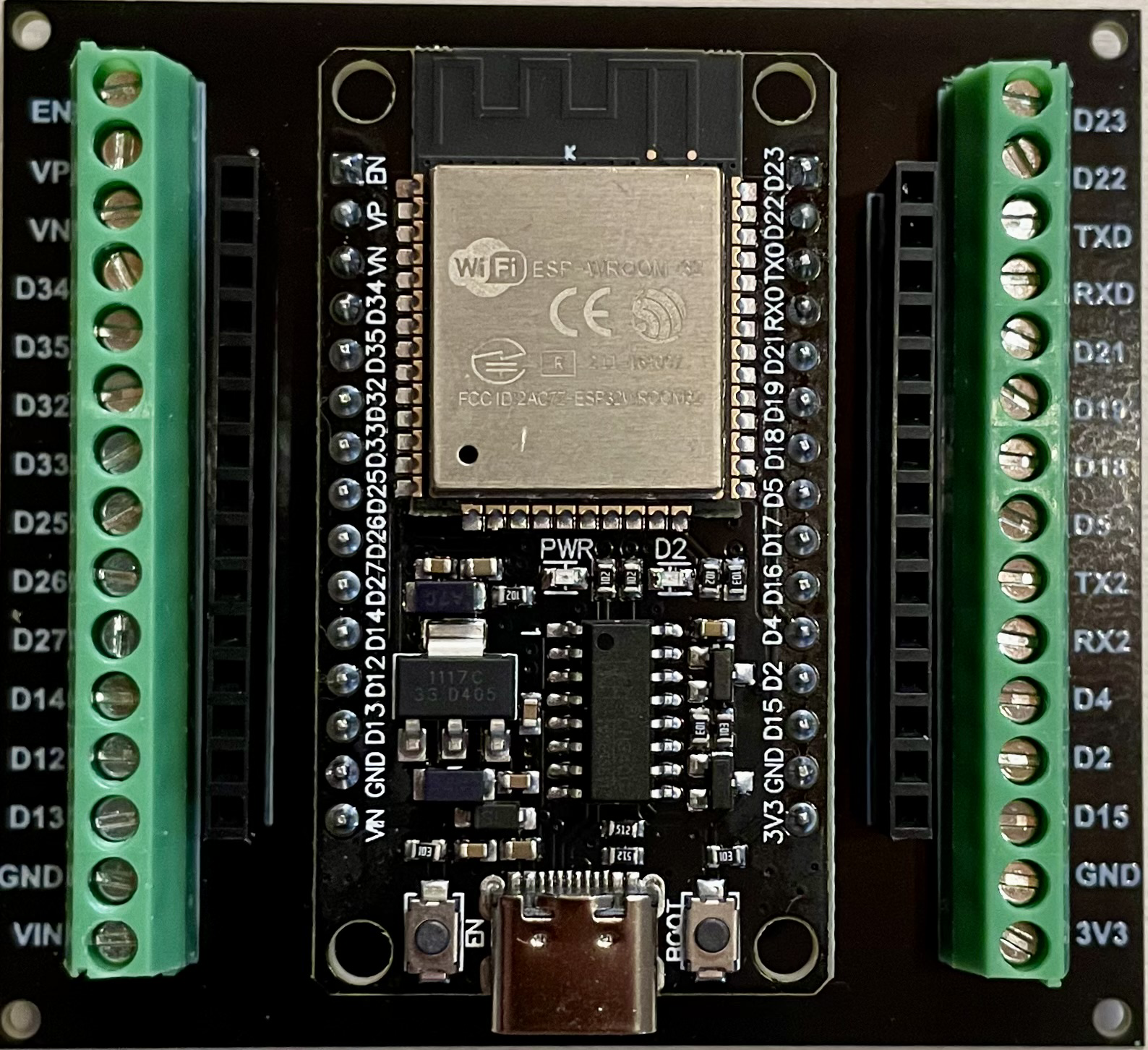
The ESP32 (30 PIN) on Breakout Board is a powerful, feature-rich microcontroller that integrates Wi-Fi and Bluetooth connectivity, making it an ideal choice for Internet of Things (IoT) projects. Its low cost, combined with a high-performance dual-core CPU and a variety of peripherals, allows for a wide range of applications, from simple home automation to complex wireless sensor networks.

Explore Projects Built with ESP32 (30 PIN) on Breakout Board

Use Cirkit Designer to design, explore, and prototype these projects online. Some projects support real-time simulation. Click "Open Project" to start designing instantly!
ESP32-Based Smart Display with Camera and Audio Alert System
Image of cam_circuit_design: A project utilizing ESP32 (30 PIN) on Breakout Board in a practical application
This circuit features two ESP32 microcontrollers, one standard 30-pin version and one ESP32-CAM module, both sharing a common ground and power supply. The 30-pin ESP32 is interfaced with an I2C LCD 16x2 Screen for display purposes, using its I2C pins (D21 for SDA and D22 for SCL), and controls a buzzer connected to pin D23. Additionally, the ESP32-CAM is connected to the 30-pin ESP32 via serial communication through pins TX2 and RX2 for potential image data transfer.
Cirkit Designer LogoOpen Project in Cirkit Designer
ESP32-Controlled OLED Display and Servo with DotStar LED Strip and Audio Output
Image of Arena 2: A project utilizing ESP32 (30 PIN) on Breakout Board in a practical application
This circuit features an ESP32 microcontroller driving a variety of components. It controls an OLED display for visual output, a DotStar LED strip for lighting effects, a PAM8403 audio amplifier connected to a speaker for sound output, and a PCA9685 PWM Servo Breakout to manage a servo motor. The ESP32 also interfaces with a piezo speaker for additional sound generation, and the circuit is powered by a 18650 Li-ion battery setup with a TP4056 charging module. The ESP32's embedded code handles the display animation on the OLED.
Cirkit Designer LogoOpen Project in Cirkit Designer
ESP32-Based OLED Display Interface
Image of d: A project utilizing ESP32 (30 PIN) on Breakout Board in a practical application
This circuit features an ESP32 microcontroller connected to an OLED 1.3" display. The ESP32's GPIO pins 21 and 22 are used for I2C communication (SDA and SCL respectively) with the OLED display. The display is powered by the 5V output from the ESP32, and both devices share a common ground.
Cirkit Designer LogoOpen Project in Cirkit Designer
ESP32-Powered NTP Clock with Multiple GC9A01 Displays
Image of InfoOrbsFork: A project utilizing ESP32 (30 PIN) on Breakout Board in a practical application
This circuit features an ESP32 microcontroller connected to multiple GC9A01 displays and a USB Type C breakout for power. The ESP32 runs a sketch to retrieve the current time from an NTP server over WiFi and displays the hours and minutes across the GC9A01 displays, with each display showing a single digit or colon separator. Pushbuttons are connected to GPIOs on the ESP32, potentially for user input to control display functions or settings.
Cirkit Designer LogoOpen Project in Cirkit Designer

Explore Projects Built with ESP32 (30 PIN) on Breakout Board

Use Cirkit Designer to design, explore, and prototype these projects online. Some projects support real-time simulation. Click "Open Project" to start designing instantly!
Image of cam_circuit_design: A project utilizing ESP32 (30 PIN) on Breakout Board in a practical application
ESP32-Based Smart Display with Camera and Audio Alert System
This circuit features two ESP32 microcontrollers, one standard 30-pin version and one ESP32-CAM module, both sharing a common ground and power supply. The 30-pin ESP32 is interfaced with an I2C LCD 16x2 Screen for display purposes, using its I2C pins (D21 for SDA and D22 for SCL), and controls a buzzer connected to pin D23. Additionally, the ESP32-CAM is connected to the 30-pin ESP32 via serial communication through pins TX2 and RX2 for potential image data transfer.
Cirkit Designer LogoOpen Project in Cirkit Designer
Image of Arena 2: A project utilizing ESP32 (30 PIN) on Breakout Board in a practical application
ESP32-Controlled OLED Display and Servo with DotStar LED Strip and Audio Output
This circuit features an ESP32 microcontroller driving a variety of components. It controls an OLED display for visual output, a DotStar LED strip for lighting effects, a PAM8403 audio amplifier connected to a speaker for sound output, and a PCA9685 PWM Servo Breakout to manage a servo motor. The ESP32 also interfaces with a piezo speaker for additional sound generation, and the circuit is powered by a 18650 Li-ion battery setup with a TP4056 charging module. The ESP32's embedded code handles the display animation on the OLED.
Cirkit Designer LogoOpen Project in Cirkit Designer
Image of d: A project utilizing ESP32 (30 PIN) on Breakout Board in a practical application
ESP32-Based OLED Display Interface
This circuit features an ESP32 microcontroller connected to an OLED 1.3" display. The ESP32's GPIO pins 21 and 22 are used for I2C communication (SDA and SCL respectively) with the OLED display. The display is powered by the 5V output from the ESP32, and both devices share a common ground.
Cirkit Designer LogoOpen Project in Cirkit Designer
Image of InfoOrbsFork: A project utilizing ESP32 (30 PIN) on Breakout Board in a practical application
ESP32-Powered NTP Clock with Multiple GC9A01 Displays
This circuit features an ESP32 microcontroller connected to multiple GC9A01 displays and a USB Type C breakout for power. The ESP32 runs a sketch to retrieve the current time from an NTP server over WiFi and displays the hours and minutes across the GC9A01 displays, with each display showing a single digit or colon separator. Pushbuttons are connected to GPIOs on the ESP32, potentially for user input to control display functions or settings.
Cirkit Designer LogoOpen Project in Cirkit Designer

Common Applications and Use Cases

  • Smart home devices
  • Wireless sensor networks
  • IoT applications
  • Wearable electronics
  • Remote-controlled toys
  • DIY projects

Technical Specifications

Key Technical Details

  • CPU: Xtensa® dual-core 32-bit LX6 microprocessor
  • Operating Voltage: 3.3V
  • Input Voltage: 7-12V (VIN pin), 5V (USB)
  • Digital I/O Pins: 22
  • Analog Input Pins: 6 (ADC channels)
  • Flash Memory: 4MB
  • SRAM: 520 KB
  • Wi-Fi: 802.11 b/g/n
  • Bluetooth: v4.2 BR/EDR and BLE
  • Clock Frequency: up to 240MHz
  • Operating Temperature: -40°C to +125°C

Pin Configuration and Descriptions

Pin Number Function Description
1-14 GPIO0 - GPIO13 General Purpose Input/Output Pins
15 ADC1_0 Analog to Digital Converter, Channel 0
16 ADC1_1 Analog to Digital Converter, Channel 1
... ... ...
30 GND Ground

Note: This is a simplified table. Please refer to the ESP32 datasheet for the complete pinout and functions.

Usage Instructions

How to Use the Component in a Circuit

  1. Powering the ESP32:

    • Connect a 7-12V power supply to the VIN pin for operation.
    • Alternatively, power the board via the micro USB port.
  2. Connecting to Wi-Fi:

    • Use the provided libraries to connect the ESP32 to a Wi-Fi network for internet access or local networking.
  3. Programming the ESP32:

    • The ESP32 can be programmed using the Arduino IDE or other development environments that support the ESP32 SDK.

Important Considerations and Best Practices

  • Always ensure that the power supply is within the specified range to prevent damage.
  • Use a decoupling capacitor close to the power pins to stabilize the power supply.
  • When designing circuits, consider the current draw from each GPIO pin and the total current draw from the board.
  • Avoid exposing the board to temperatures outside the specified operating range.
  • Update the firmware and libraries to the latest versions for optimal performance and security.

Troubleshooting and FAQs

Common Issues Users Might Face

  • ESP32 not booting up: Ensure that the power supply is connected correctly and is within the specified voltage range.
  • Wi-Fi connection issues: Check the SSID and password, and ensure that the Wi-Fi signal strength is adequate.
  • Programming errors: Verify that the correct board and port are selected in the development environment.

Solutions and Tips for Troubleshooting

  • If the ESP32 is unresponsive, try resetting the board or re-flashing the firmware.
  • For Wi-Fi issues, try moving the ESP32 closer to the router or adding an external antenna if the board supports it.
  • Consult the ESP32 forums and communities for support and advice on specific programming issues.

Example Code for Arduino UNO

#include <WiFi.h>

// Replace with your network credentials
const char* ssid = "your_SSID";
const char* password = "your_PASSWORD";

void setup() {
  Serial.begin(115200);
  
  // Connect to Wi-Fi
  WiFi.begin(ssid, password);
  while (WiFi.status() != WL_CONNECTED) {
    delay(500);
    Serial.println("Connecting to WiFi...");
  }
  Serial.println("Connected to WiFi");
}

void loop() {
  // Your code here
}

Note: This example demonstrates how to connect the ESP32 to a Wi-Fi network. Ensure that you have the appropriate libraries installed in your Arduino IDE.

Remember to follow the 80 character limit for code comments, wrapping text as needed. This example adheres to that guideline.