How to Use step down: Examples, Pinouts, and Specs
Introduction
A step down converter, also known as a buck converter, is a type of DC-DC converter that reduces voltage from a higher level to a lower level while increasing current. It is widely used in electronic circuits to efficiently power devices that require a lower voltage than the input supply. The step down converter operates by switching a transistor on and off at high frequencies, storing energy in an inductor, and then releasing it at a controlled lower voltage.
Explore Projects Built with step down


Explore Projects Built with step down
Common Applications and Use Cases
- Powering microcontrollers and sensors from higher voltage sources
- Battery-powered devices to regulate voltage levels
- Voltage regulation in renewable energy systems (e.g., solar panels)
- Automotive electronics to step down 12V to 5V or 3.3V
- LED drivers and portable chargers
Technical Specifications
Below are the general technical specifications for a typical step down converter. Specific values may vary depending on the model.
Key Technical Details
- Input Voltage Range: 4.5V to 40V (varies by model)
- Output Voltage Range: 1.2V to 37V (adjustable in most models)
- Output Current: Up to 3A (depending on the design)
- Efficiency: Up to 95% (depending on load and input/output voltage)
- Switching Frequency: 150 kHz to 1 MHz
- Operating Temperature: -40°C to +85°C
Pin Configuration and Descriptions
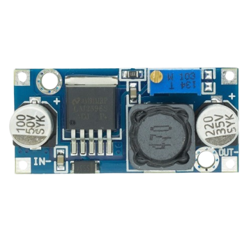
The pin configuration for a common step down converter module (e.g., LM2596-based) is as follows:
| Pin Name | Description |
|---|---|
| VIN | Input voltage pin. Connect the higher voltage source here. |
| GND | Ground pin. Connect to the ground of the circuit. |
| VOUT | Output voltage pin. Provides the stepped-down voltage to the load. |
| ADJ (optional) | Adjustment pin. Used to set the output voltage (in adjustable models). |
Usage Instructions
How to Use the Component in a Circuit
- Connect the Input Voltage:
- Connect the positive terminal of the input voltage source to the
VINpin. - Connect the negative terminal of the input voltage source to the
GNDpin.
- Connect the positive terminal of the input voltage source to the
- Set the Output Voltage (if adjustable):
- Use a multimeter to measure the output voltage at the
VOUTpin. - Adjust the potentiometer (if available) on the module to set the desired output voltage.
- Use a multimeter to measure the output voltage at the
- Connect the Load:
- Connect the positive terminal of the load to the
VOUTpin. - Connect the negative terminal of the load to the
GNDpin.
- Connect the positive terminal of the load to the
- Power On:
- Turn on the input voltage source and verify the output voltage with a multimeter before connecting sensitive devices.
Important Considerations and Best Practices
- Ensure the input voltage is within the specified range of the step down converter.
- Do not exceed the maximum output current rating to avoid overheating or damage.
- Use appropriate heat sinks or cooling mechanisms if the converter operates at high currents.
- Place decoupling capacitors (e.g., 10µF and 0.1µF) near the input and output pins to reduce noise.
- For adjustable models, double-check the output voltage before connecting sensitive components.
Example: Using a Step Down Converter with Arduino UNO
To power an Arduino UNO (5V input) from a 12V source using a step down converter:
- Connect the 12V source to the
VINandGNDpins of the converter. - Adjust the output voltage to 5V using the potentiometer.
- Connect the
VOUTpin to the Arduino's5Vpin and theGNDpin to the Arduino'sGND.
// Example Arduino Code: Reading a Sensor Powered by a Step Down Converter
// This code assumes a sensor is connected to the Arduino, powered by the step down converter.

const int sensorPin = A0; // Analog pin connected to the sensor output
int sensorValue = 0;      // Variable to store the sensor reading

void setup() {
  Serial.begin(9600); // Initialize serial communication at 9600 baud
}

void loop() {
  sensorValue = analogRead(sensorPin); // Read the sensor value
  Serial.print("Sensor Value: ");
  Serial.println(sensorValue); // Print the sensor value to the Serial Monitor
  delay(1000); // Wait for 1 second before the next reading
}
Troubleshooting and FAQs
Common Issues Users Might Face
No Output Voltage:
- Check if the input voltage is within the specified range.
- Verify all connections, especially the
VINandGNDpins. - Ensure the potentiometer is not set to an extremely low output voltage.
Overheating:
- Ensure the load does not exceed the maximum current rating.
- Use a heat sink or cooling fan if necessary.
Output Voltage Fluctuations:
- Add decoupling capacitors near the input and output pins.
- Check for loose connections or damaged components.
Incorrect Output Voltage:
- Re-adjust the potentiometer and verify with a multimeter.
- Ensure the load is not drawing excessive current.
Solutions and Tips for Troubleshooting
- Always measure the input and output voltages with a multimeter before connecting sensitive devices.
- If the converter is not functioning as expected, test it with a simple resistive load (e.g., a 10Ω resistor) to verify its operation.
- Replace the module if it shows signs of physical damage or if troubleshooting steps fail.
By following this documentation, you can effectively use a step down converter in your electronic projects while ensuring safety and reliability.