How to Use ESP32 devkit v1: Examples, Pinouts, and Specs
Introduction
The ESP32 DevKit V1, manufactured by Espressif, is a versatile development board built around the powerful ESP32 chip. It features integrated Wi-Fi and Bluetooth capabilities, making it an excellent choice for Internet of Things (IoT) applications, smart devices, and rapid prototyping. The board is compact, cost-effective, and supports a wide range of peripherals, making it suitable for both beginners and experienced developers.
Explore Projects Built with ESP32 devkit v1


Explore Projects Built with ESP32 devkit v1
Common Applications and Use Cases
- IoT devices and smart home automation
- Wireless sensor networks
- Wearable technology
- Robotics and automation
- Prototyping for Wi-Fi and Bluetooth-enabled projects
- Data logging and remote monitoring systems
Technical Specifications
The ESP32 DevKit V1 is equipped with the ESP32-WROOM-32 module, which includes a dual-core processor and a rich set of features. Below are the key technical specifications:
| Specification | Details |
|---|---|
| Microcontroller | ESP32 (Xtensa® 32-bit LX6 dual-core processor) |
| Clock Speed | Up to 240 MHz |
| Flash Memory | 4 MB (varies by model) |
| SRAM | 520 KB |
| Wi-Fi | 802.11 b/g/n (2.4 GHz) |
| Bluetooth | Bluetooth 4.2 (Classic and BLE) |
| Operating Voltage | 3.3V |
| Input Voltage (VIN) | 5V (via USB or external power supply) |
| GPIO Pins | 30 (varies slightly by board version) |
| ADC Channels | 18 (12-bit resolution) |
| DAC Channels | 2 |
| Communication Interfaces | UART, SPI, I2C, I2S, CAN, PWM |
| Power Consumption | Ultra-low power consumption with multiple power modes |
| Dimensions | Approx. 54 mm x 27 mm |
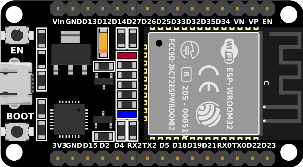
Pin Configuration and Descriptions
The ESP32 DevKit V1 has a total of 30 pins, with various functionalities. Below is the pinout description:
| Pin | Name | Function |
|---|---|---|
| 1 | EN | Reset the chip (active high) |
| 2 | GND | Ground |
| 3 | VIN | Input voltage (5V) |
| 4-39 | GPIO0-GPIO39 | General-purpose input/output pins (various functions: ADC, PWM, I2C, etc.) |
| 40 | 3V3 | 3.3V output |
| 41 | TX0/RX0 | UART0 (default serial communication pins) |
| 42 | TX1/RX1 | UART1 (alternative serial communication pins) |
| 43 | TX2/RX2 | UART2 (alternative serial communication pins) |
| 44 | DAC1/DAC2 | Digital-to-Analog Converter pins |
| 45 | ADC1/ADC2 | Analog-to-Digital Converter pins |
Note: The exact pinout may vary slightly depending on the specific version of the ESP32 DevKit V1.
Usage Instructions
How to Use the ESP32 DevKit V1 in a Circuit
Powering the Board:
- Connect the board to your computer via a micro-USB cable for power and programming.
- Alternatively, supply 5V to the VIN pin or 3.3V to the 3V3 pin for external power.
Programming the Board:
- Install the Arduino IDE or Espressif's ESP-IDF for development.
- Add the ESP32 board support package to the Arduino IDE via the Board Manager.
- Select "ESP32 Dev Module" as the board in the Arduino IDE.
Connecting Peripherals:
- Use the GPIO pins to connect sensors, actuators, or other peripherals.
- Ensure that the voltage levels of connected devices are compatible with the ESP32 (3.3V logic).
Uploading Code:
- Write your code in the Arduino IDE or ESP-IDF.
- Connect the board to your computer and select the correct COM port.
- Click the upload button to flash the code onto the ESP32.
Example Code: Blinking an LED
The following example demonstrates how to blink an LED connected to GPIO2 of the ESP32 DevKit V1.
// Example: Blink an LED connected to GPIO2 on the ESP32 DevKit V1

// Define the GPIO pin where the LED is connected
const int ledPin = 2;

void setup() {
  // Set the LED pin as an output
  pinMode(ledPin, OUTPUT);
}

void loop() {
  // Turn the LED on
  digitalWrite(ledPin, HIGH);
  delay(1000); // Wait for 1 second

  // Turn the LED off
  digitalWrite(ledPin, LOW);
  delay(1000); // Wait for 1 second
}
Important Considerations and Best Practices
- Voltage Levels: Ensure all connected peripherals operate at 3.3V logic levels to avoid damaging the ESP32.
- Boot Mode: GPIO0 must be pulled low during boot to enter programming mode.
- Power Supply: Use a stable power source to avoid unexpected resets or instability.
- Wi-Fi and Bluetooth: Avoid placing the board near metal objects or enclosures that may interfere with wireless signals.
Troubleshooting and FAQs
Common Issues and Solutions
The board is not detected by the computer:
- Ensure the USB cable is functional and supports data transfer.
- Install the correct USB-to-serial driver (e.g., CP2102 or CH340, depending on the board).
Code upload fails:
- Check that the correct COM port and board are selected in the Arduino IDE.
- Hold the "BOOT" button on the board while uploading the code.
Wi-Fi connection issues:
- Verify the SSID and password in your code.
- Ensure the Wi-Fi network operates on the 2.4 GHz band (ESP32 does not support 5 GHz).
Random resets or instability:
- Use a stable power supply with sufficient current (at least 500 mA).
- Check for loose connections or short circuits.
FAQs
Q: Can I use the ESP32 DevKit V1 with a 5V sensor?
A: Yes, but you will need a level shifter to convert the 5V logic to 3.3V.
Q: How do I reset the ESP32?
A: Press the "EN" button on the board to reset the chip.
Q: Can I use the ESP32 DevKit V1 for battery-powered projects?
A: Yes, the board supports low-power modes, making it suitable for battery-powered applications.
Q: What is the maximum range of the ESP32's Wi-Fi?
A: The range depends on the environment but typically extends up to 100 meters in open spaces.
By following this documentation, you can effectively utilize the ESP32 DevKit V1 for a wide range of applications.