How to Use RF 433: Examples, Pinouts, and Specs
Introduction
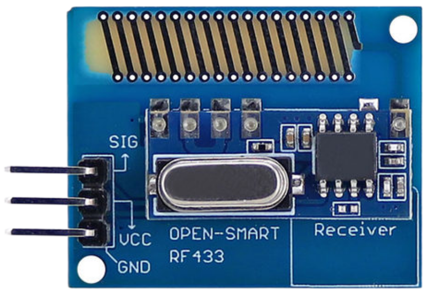
The RF 433 Receiver, manufactured by Open-Smart (Part ID: RF 433 RECEIVER), is a radio frequency module designed for wireless communication at 433 MHz. It is widely used in low-power applications such as remote controls, wireless sensors, home automation systems, and IoT devices. This module enables devices to communicate wirelessly over short to medium distances, making it ideal for projects requiring simple and cost-effective wireless communication.
Explore Projects Built with RF 433


Explore Projects Built with RF 433
Common Applications
- Wireless remote controls (e.g., garage doors, fans, and lights)
- Home automation systems
- Wireless sensor networks
- Internet of Things (IoT) devices
- Data transmission between microcontrollers
Technical Specifications
The RF 433 Receiver module is designed for efficient and reliable wireless communication. Below are its key technical details:
| Parameter | Value |
|---|---|
| Operating Frequency | 433 MHz |
| Operating Voltage | 5V DC |
| Operating Current | ≤5 mA |
| Sensitivity | -105 dBm |
| Data Rate | 2 kbps (maximum) |
| Communication Range | Up to 100 meters (line of sight) |
| Modulation Technique | Amplitude Shift Keying (ASK) |
| Dimensions | 30 mm x 14 mm x 7 mm |
Pin Configuration and Descriptions
The RF 433 Receiver module has four pins, as described in the table below:
| Pin Name | Pin Number | Description |
|---|---|---|
| VCC | 1 | Power supply pin. Connect to 5V DC. |
| GND | 2 | Ground pin. Connect to the ground of the circuit. |
| DATA | 3 | Data output pin. Outputs the received signal. |
| ANT | 4 | Antenna pin. Connect to a wire or antenna for better reception. |
Usage Instructions
How to Use the RF 433 Receiver in a Circuit
- Power the Module: Connect the
VCCpin to a 5V DC power source and theGNDpin to the ground. - Connect the Data Pin: Connect the
DATApin to the input pin of a microcontroller (e.g., Arduino UNO) or a decoder IC. - Attach an Antenna: For optimal performance, connect a 17 cm wire to the
ANTpin to act as an antenna. - Pair with a Transmitter: Ensure the RF 433 Receiver is paired with a compatible 433 MHz transmitter module for communication.
- Decode the Signal: Use a microcontroller or decoder IC to process the received data.
Important Considerations and Best Practices
- Antenna Placement: Ensure the antenna is placed away from metal objects to avoid interference.
- Power Supply: Use a stable 5V power source to prevent noise and ensure reliable operation.
- Line of Sight: For maximum range, maintain a clear line of sight between the transmitter and receiver.
- Data Decoding: Use libraries like
RC-Switchfor Arduino to simplify signal decoding.
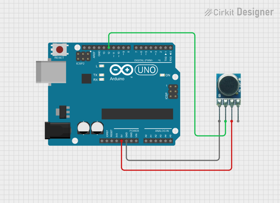
Example: Connecting RF 433 Receiver to Arduino UNO
Below is an example of how to use the RF 433 Receiver with an Arduino UNO to receive data:
#include <RCSwitch.h> // Include the RC-Switch library

RCSwitch mySwitch = RCSwitch(); // Create an instance of RCSwitch

void setup() {
  Serial.begin(9600); // Initialize serial communication at 9600 baud
  mySwitch.enableReceive(0); // Enable receiver on interrupt pin 2 (Arduino UNO pin 2)
}

void loop() {
  if (mySwitch.available()) { // Check if data is received
    int value = mySwitch.getReceivedValue(); // Get the received value

    if (value == 0) {
      Serial.println("Unknown signal"); // Print error if signal is invalid
    } else {
      Serial.print("Received: ");
      Serial.println(value); // Print the received value
    }

    mySwitch.resetAvailable(); // Reset the receiver for the next signal
  }
}
Notes:
- Install the
RC-Switchlibrary in the Arduino IDE before uploading the code. - Connect the
DATApin of the RF 433 Receiver to Arduino pin 2.
Troubleshooting and FAQs
Common Issues and Solutions
No Signal Received
- Cause: Poor antenna connection or placement.
- Solution: Ensure the antenna is securely connected and positioned away from interference sources.
Short Communication Range
- Cause: Obstacles or weak power supply.
- Solution: Use a clear line of sight and ensure a stable 5V power supply.
Interference from Other Devices
- Cause: Nearby devices operating at 433 MHz.
- Solution: Test in a less crowded frequency environment or use filters to reduce noise.
Unstable Data Output
- Cause: Noise in the power supply or weak signal.
- Solution: Use decoupling capacitors near the power pins and improve the antenna design.
FAQs
Q1: Can the RF 433 Receiver work with a 3.3V power supply?
A1: No, the RF 433 Receiver requires a 5V power supply for proper operation.
Q2: What is the maximum range of the RF 433 Receiver?
A2: The maximum range is approximately 100 meters in an open, line-of-sight environment. Obstacles and interference can reduce this range.
Q3: Can I use multiple RF 433 Receivers in the same area?
A3: Yes, but ensure that each receiver is paired with a unique transmitter to avoid interference.
Q4: How do I improve the signal quality?
A4: Use a longer antenna (17 cm for 433 MHz), ensure a stable power supply, and minimize interference from nearby devices.
This documentation provides a comprehensive guide to using the RF 433 Receiver module effectively in your projects.