How to Use Adafruit Arcade Bonnet: Examples, Pinouts, and Specs
Introduction
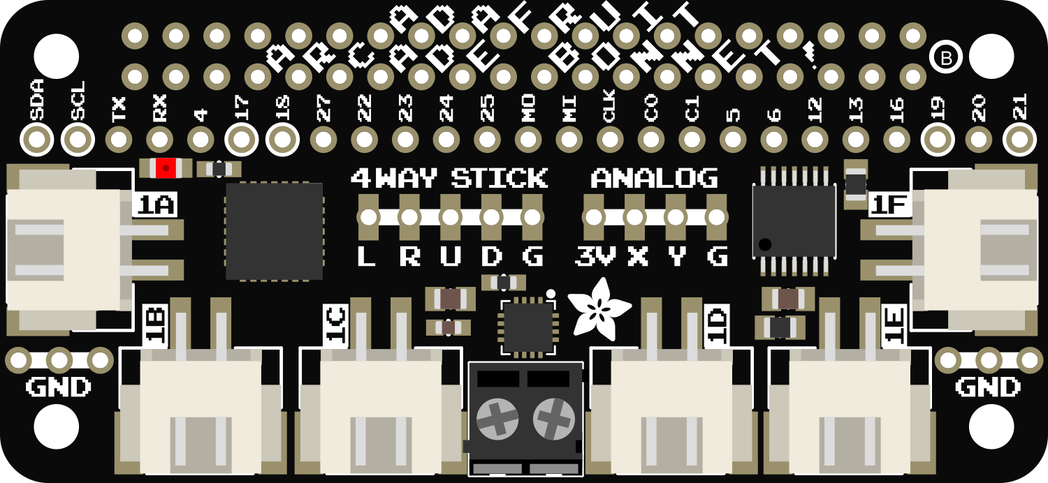
The Adafruit Arcade Bonnet is an essential component for arcade enthusiasts and DIY hobbyists looking to create their own arcade cabinets or controllers. This compact add-on board is designed specifically for the Raspberry Pi, offering an easy-to-use interface for connecting arcade buttons and joysticks. With the Arcade Bonnet, users can transform their Raspberry Pi into the brain of a retro gaming system, enabling them to play classic arcade games with authentic controls.
Explore Projects Built with Adafruit Arcade Bonnet
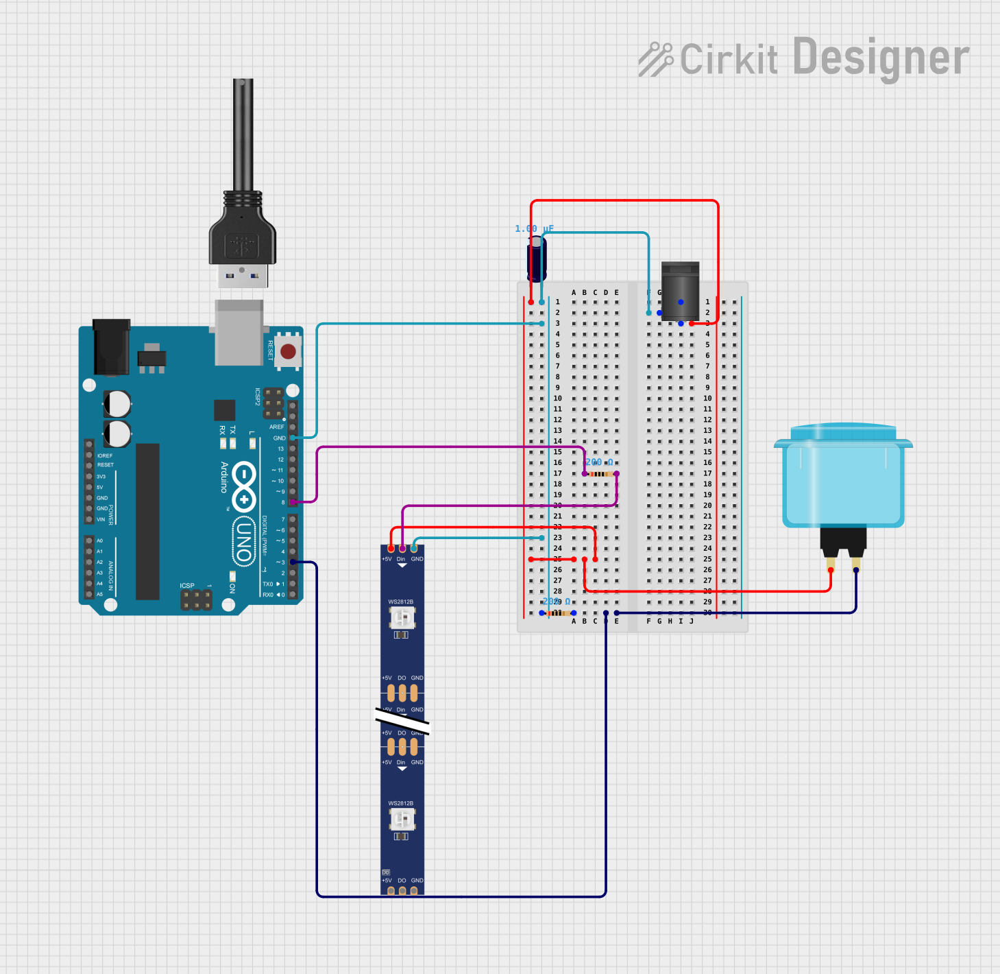
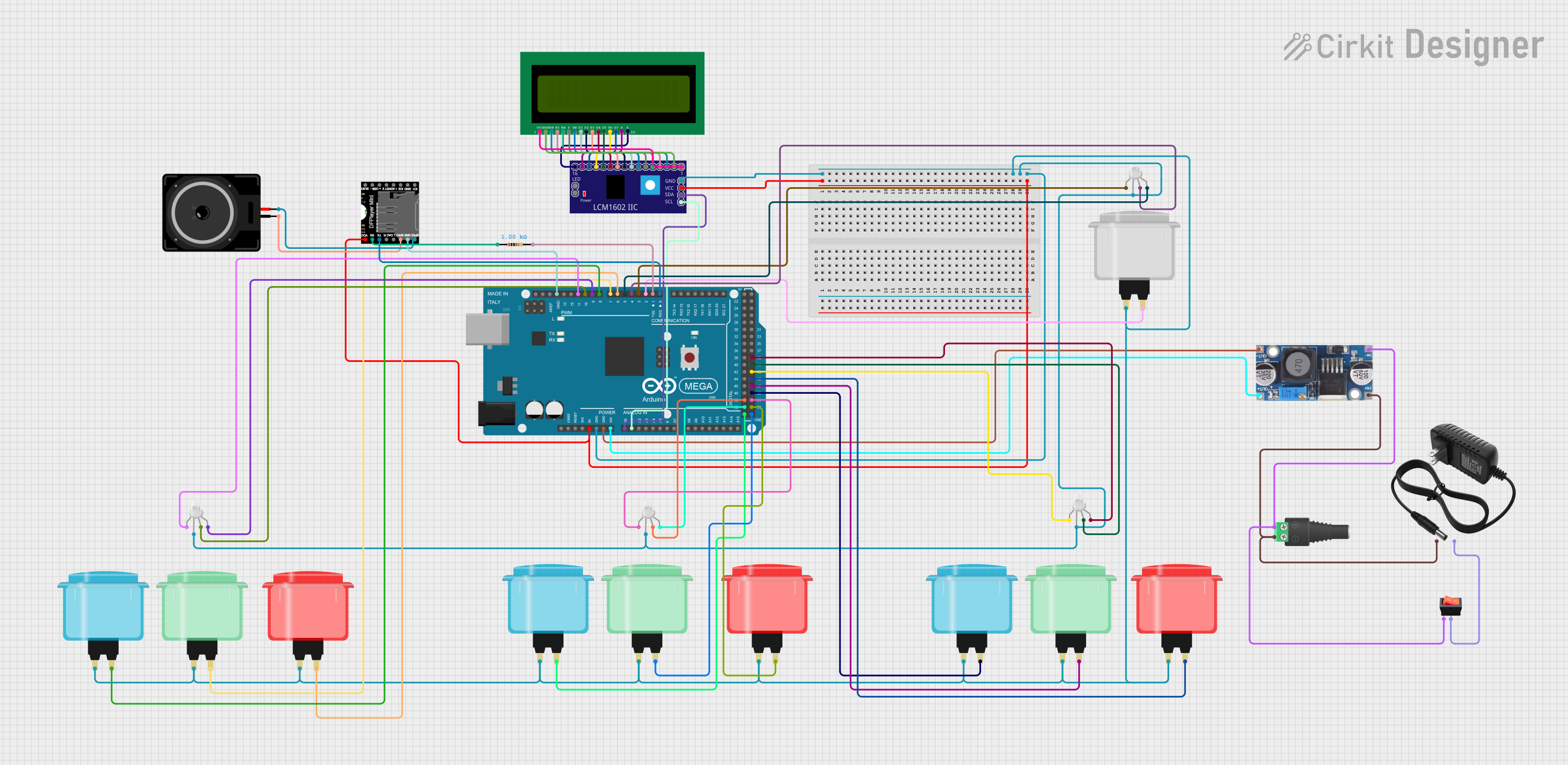

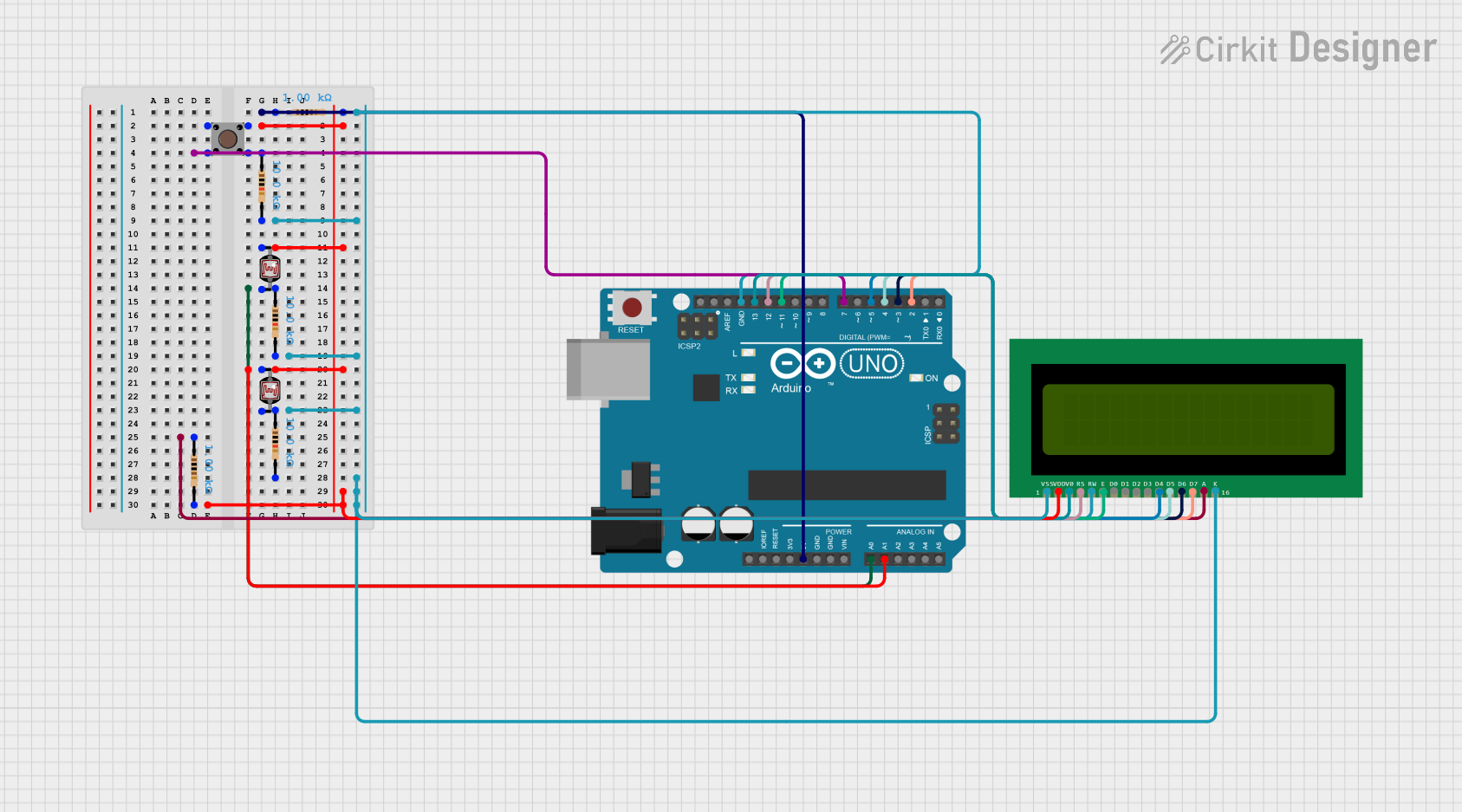
Explore Projects Built with Adafruit Arcade Bonnet
Common Applications and Use Cases
- DIY arcade cabinets
- Custom-built arcade controllers
- Retro gaming stations
- Educational projects for learning about game hardware
- Interactive installations and exhibits
Technical Specifications
Key Technical Details
- Operating Voltage: 5V (supplied by the Raspberry Pi)
- Current Rating: Varies depending on the number and type of connected peripherals
- Interface: Connects via GPIO pins on the Raspberry Pi
- Dimensions: 65mm x 30mm x 10mm (L x W x H)
Pin Configuration and Descriptions
| Pin Number | Description | Notes |
|---|---|---|
| 1 | 5V Power | Supplied by Raspberry Pi |
| 2 | Ground | Common ground for all controls |
| 3-12 | Button Inputs | Configurable for arcade buttons |
| 13-16 | Joystick Inputs | For directional control |
| 17 | Additional Ground (optional) | For complex setups |
| 18 | I2C/SPI (optional) | For expansion modules |
Usage Instructions
How to Use the Component in a Circuit
Connect the Arcade Bonnet to the Raspberry Pi: Carefully align the GPIO pins on the Arcade Bonnet with the corresponding pins on the Raspberry Pi and press down to secure the connection.
Connect Arcade Buttons and Joysticks: Wire your arcade buttons and joystick to the designated pins on the Arcade Bonnet. Ensure that each button and joystick direction has one side connected to a ground pin.
Configure Software: Install and configure the necessary software on the Raspberry Pi to recognize the inputs from the Arcade Bonnet. This typically involves setting up a game emulator and mapping the controls.
Important Considerations and Best Practices
- Power Supply: Ensure that your Raspberry Pi has a sufficient power supply to handle the Arcade Bonnet and any connected peripherals.
- Wiring: Use proper wiring techniques to avoid shorts and ensure reliable connections.
- Software Configuration: Familiarize yourself with the software you are using for emulation and input mapping to get the best gaming experience.
- Updates: Keep your Raspberry Pi and Arcade Bonnet firmware up to date to ensure compatibility and performance.
Troubleshooting and FAQs
Common Issues Users Might Face
- Unresponsive Buttons: Check the wiring connections and ensure that each button is properly connected to its designated pin and ground.
- Joystick Not Working: Verify that the joystick is wired correctly and that the software is configured to recognize the joystick inputs.
- Intermittent Connectivity: Inspect the GPIO connection between the Arcade Bonnet and the Raspberry Pi for any loose connections or debris.
Solutions and Tips for Troubleshooting
- Recheck Wiring: Double-check all connections for continuity and proper contact.
- Software Reconfiguration: Revisit the input mapping settings in your emulator software to ensure all controls are correctly assigned.
- Update Firmware: Make sure the Raspberry Pi and any related software are fully updated.
FAQs
Q: Can I use the Arcade Bonnet with any Raspberry Pi model? A: The Arcade Bonnet is compatible with Raspberry Pi models that have a 40-pin GPIO header. Check the Adafruit website for specific model compatibility.
Q: How many buttons can I connect to the Arcade Bonnet? A: The Arcade Bonnet supports up to 12 button inputs, allowing for a versatile range of control configurations.
Q: Do I need to install drivers for the Arcade Bonnet? A: No drivers are necessary, but you will need to configure your emulator software to recognize the inputs from the Arcade Bonnet.
Q: Can I connect more than one joystick to the Arcade Bonnet? A: The Arcade Bonnet is designed to support one joystick out of the box. For additional joysticks, you may need to use expansion modules or additional hardware.
Example Code for Raspberry Pi
Below is an example Python script that demonstrates how to read inputs from the Arcade Bonnet using the GPIO library. This script assumes you have already installed the necessary libraries and configured your Raspberry Pi for GPIO access.
import RPi.GPIO as GPIO
import time
Set up GPIO using BCM numbering
GPIO.setmode(GPIO.BCM)
Define button and joystick pins (replace with your actual pin numbers)
button_pins = [3, 4, 5, 6, 7, 8, 9, 10, 11, 12] joystick_pins = [13, 14, 15, 16]
Set up pins as inputs with pull-up resistors
for pin in button_pins + joystick_pins: GPIO.setup(pin, GPIO.IN, pull_up_down=GPIO.PUD_UP)
try: while True: # Read the state of each input for pin in button_pins: if GPIO.input(pin) == False: print(f"Button {pin} pressed") time.sleep(0.2) # Debounce delay
    for pin in joystick_pins:
        if GPIO.input(pin) == False:
            print(f"Joystick direction {pin} activated")
            time.sleep(0.2)  # Debounce delay
except KeyboardInterrupt: # Clean up GPIO on CTRL+C exit GPIO.cleanup()
Clean up GPIO on normal exit
GPIO.cleanup()
Remember to replace the `button_pins` and `joystick_pins` lists with the actual GPIO pin numbers you are using for your buttons and joystick. This script will print a message to the console whenever a button is pressed or a joystick direction is activated.