How to Use BUCK CONVERTER: Examples, Pinouts, and Specs
Introduction
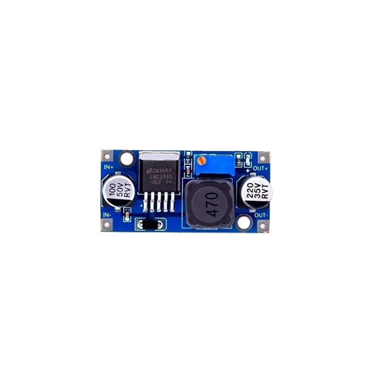
A buck converter is a type of DC-DC converter that steps down voltage while stepping up current. It achieves this by using a combination of a switching element (such as a transistor), a diode, an inductor, and a capacitor. Buck converters are highly efficient and are widely used in applications where a stable, lower voltage is required from a higher voltage source.
Explore Projects Built with BUCK CONVERTER


Explore Projects Built with BUCK CONVERTER
Common Applications and Use Cases
- Powering microcontrollers and low-voltage devices from higher voltage sources
- Battery-powered systems to regulate voltage levels
- Voltage regulation in renewable energy systems (e.g., solar panels)
- Automotive electronics to step down 12V to lower voltages
- LED drivers and portable electronic devices
Technical Specifications
Below are the general technical specifications for a typical buck converter module. Specifications may vary depending on the specific model.
| Parameter | Value |
|---|---|
| Input Voltage Range | 4.5V to 40V |
| Output Voltage Range | 1.25V to 37V (adjustable via potentiometer) |
| Output Current | Up to 3A (depending on the model) |
| Efficiency | Up to 92% |
| Switching Frequency | 150 kHz |
| Operating Temperature | -40°C to +85°C |
Pin Configuration and Descriptions
| Pin Name | Description |
|---|---|
| VIN | Input voltage pin. Connect to the higher voltage source. |
| GND | Ground pin. Connect to the ground of the circuit. |
| VOUT | Output voltage pin. Provides the stepped-down voltage. |
| ADJ (optional) | Adjustment pin. Used to set the output voltage (if available). |
Usage Instructions
How to Use the Buck Converter in a Circuit
Connect the Input Voltage (VIN):
- Connect the positive terminal of the input voltage source to the
VINpin. - Connect the negative terminal of the input voltage source to the
GNDpin.
- Connect the positive terminal of the input voltage source to the
Set the Output Voltage:
- If the buck converter has an adjustable output, use the onboard potentiometer to set the desired output voltage.
- Measure the output voltage at the
VOUTpin using a multimeter while adjusting the potentiometer.
Connect the Load:
- Connect the positive terminal of the load to the
VOUTpin. - Connect the negative terminal of the load to the
GNDpin.
- Connect the positive terminal of the load to the
Power On:
- Turn on the input voltage source. The buck converter will step down the input voltage to the desired output voltage.
Important Considerations and Best Practices
- Input Voltage Range: Ensure the input voltage is within the specified range of the buck converter module.
- Output Current Limit: Do not exceed the maximum output current rating to avoid overheating or damage.
- Heat Dissipation: For high-power applications, consider adding a heatsink to the module to improve heat dissipation.
- Ripple and Noise: Use additional capacitors at the input and output to reduce voltage ripple and noise.
- Polarity: Double-check the polarity of the connections to avoid damaging the module.
Example: Using a Buck Converter with an Arduino UNO
Below is an example of how to use a buck converter to power an Arduino UNO from a 12V source.
Circuit Connections
- Connect the 12V source to the
VINandGNDpins of the buck converter. - Adjust the output voltage of the buck converter to 5V using the potentiometer.
- Connect the
VOUTpin of the buck converter to the5Vpin of the Arduino UNO. - Connect the
GNDpin of the buck converter to theGNDpin of the Arduino UNO.
Arduino Code Example
// Example code to blink an LED connected to pin 13 of the Arduino UNO
// Ensure the Arduino is powered via the buck converter (5V output).

void setup() {
  pinMode(13, OUTPUT); // Set pin 13 as an output pin
}

void loop() {
  digitalWrite(13, HIGH); // Turn the LED on
  delay(1000);            // Wait for 1 second
  digitalWrite(13, LOW);  // Turn the LED off
  delay(1000);            // Wait for 1 second
}
Troubleshooting and FAQs
Common Issues and Solutions
No Output Voltage:
- Cause: Incorrect wiring or polarity.
- Solution: Double-check all connections and ensure the input voltage is within the specified range.
Output Voltage is Incorrect:
- Cause: Potentiometer not adjusted properly.
- Solution: Use a multimeter to measure the output voltage and adjust the potentiometer.
Overheating:
- Cause: Exceeding the maximum current rating or insufficient heat dissipation.
- Solution: Reduce the load current or add a heatsink to the module.
High Ripple or Noise:
- Cause: Insufficient filtering.
- Solution: Add additional capacitors (e.g., 100µF electrolytic and 0.1µF ceramic) at the input and output.
FAQs
Q: Can I use a buck converter to power a Raspberry Pi?
A: Yes, but ensure the output voltage is set to 5V and the current rating is sufficient (at least 2.5A for most Raspberry Pi models).Q: Can I use a buck converter to step down AC voltage?
A: No, buck converters are designed for DC input only. Use a transformer and rectifier for AC to DC conversion.Q: How do I know if the buck converter is overloaded?
A: Symptoms of overloading include overheating, voltage drop, or the module shutting down. Reduce the load to resolve the issue.