Cirkit Designer Logo
Cirkit Designer
Your all-in-one circuit design IDE
Home / 
Component Documentation

How to Use 5V, 5.5A Step-Down Voltage Regulator D36V50F5: Examples, Pinouts, and Specs

Image of 5V, 5.5A Step-Down Voltage Regulator D36V50F5
Cirkit Designer LogoDesign with 5V, 5.5A Step-Down Voltage Regulator D36V50F5 in Cirkit Designer

Introduction

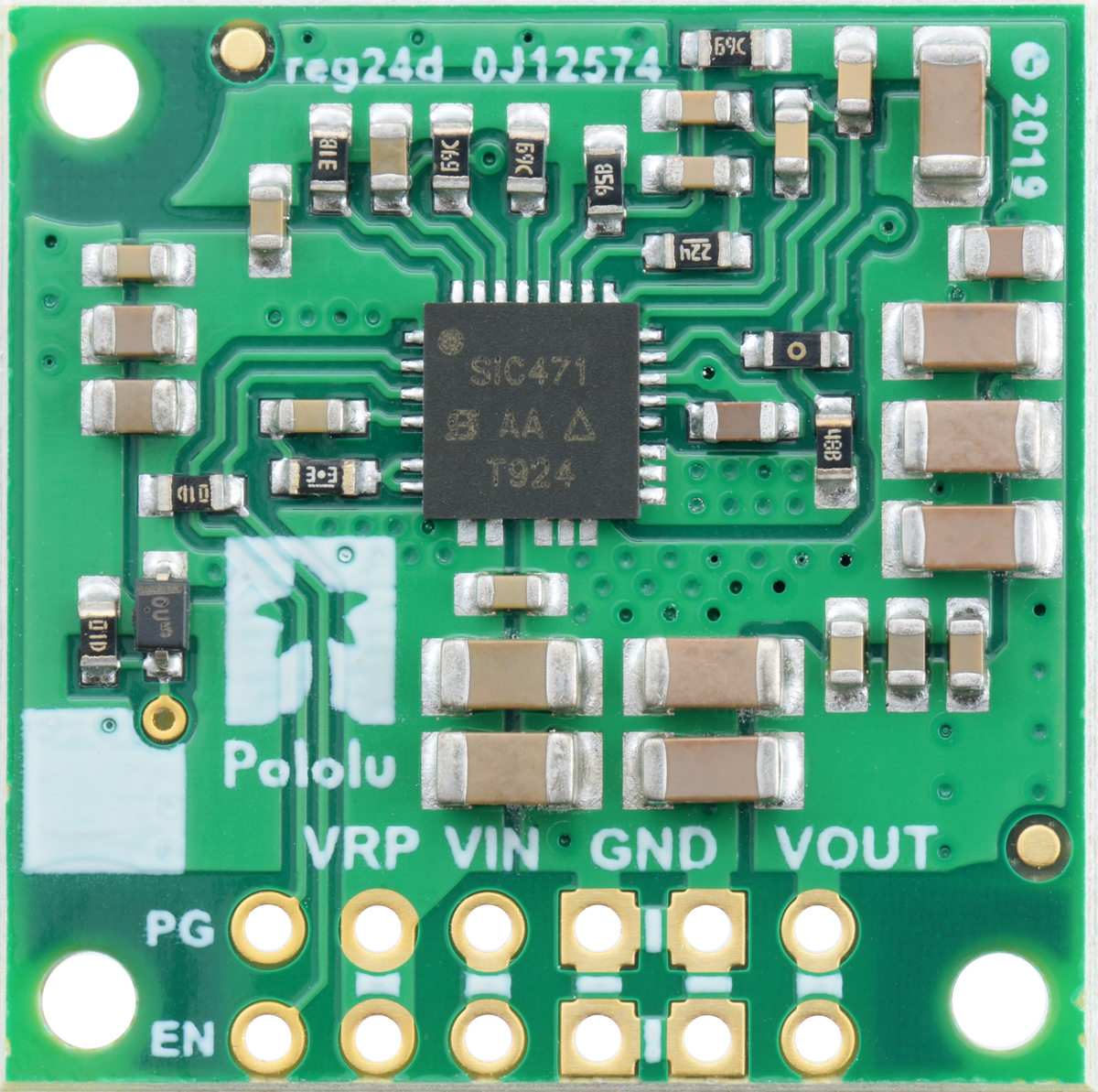
The 5V, 5.5A Step-Down Voltage Regulator D36V50F5 by Pololu is a high-efficiency, switch-mode buck regulator that converts an input voltage of up to 50V down to 5V with a maximum output current of 5.5A. This component is ideal for powering 5V electronics from a higher voltage source and is commonly used in robotics, automotive applications, and portable power devices.

Explore Projects Built with 5V, 5.5A Step-Down Voltage Regulator D36V50F5

Use Cirkit Designer to design, explore, and prototype these projects online. Some projects support real-time simulation. Click "Open Project" to start designing instantly!
12V to 5V Power Supply with LED Indicator and Push Switch
Image of Power Supply LVCO: A project utilizing 5V, 5.5A Step-Down Voltage Regulator D36V50F5 in a practical application
This circuit is a 12V to 5V regulated power supply with an LED indicator. It uses a 5408 diode for reverse polarity protection, an LM340T5 7805 voltage regulator to step down the voltage to 5V, and a push switch to control the LED indicator. The circuit also includes capacitors for filtering and a resistor to limit the current through the LED.
Cirkit Designer LogoOpen Project in Cirkit Designer
Battery-Powered USB Charger with LED Indicator and DC Motor
Image of Copy of Hand Crank mobile charger : A project utilizing 5V, 5.5A Step-Down Voltage Regulator D36V50F5 in a practical application
This circuit converts AC power to DC using a bridge rectifier and regulates the voltage to 5V with a 7805 voltage regulator. It powers a USB port and indicates power status with an LED, while also providing a charging interface through a multi-charging cable.
Cirkit Designer LogoOpen Project in Cirkit Designer
24V to 5V Power Supply with 7805 Voltage Regulator and Bridge Rectifier
Image of convert AC to DC: A project utilizing 5V, 5.5A Step-Down Voltage Regulator D36V50F5 in a practical application
This circuit converts 220V AC to 5V DC using a power transformer, a bridge rectifier, and a 7805 voltage regulator. The transformer steps down the voltage to 24V AC, which is then rectified to DC by the bridge rectifier. The 7805 regulator further stabilizes the output to 5V DC, with additional filtering provided by capacitors and a resistor.
Cirkit Designer LogoOpen Project in Cirkit Designer
24V to 5V Power Supply Using 7805 and Bridge Rectifier
Image of evs transmitter: A project utilizing 5V, 5.5A Step-Down Voltage Regulator D36V50F5 in a practical application
This circuit converts a 220V AC input to a regulated 5V DC output. It uses a power transformer to step down the voltage to 24V AC, which is then rectified by a bridge rectifier and regulated by a 7805 voltage regulator.
Cirkit Designer LogoOpen Project in Cirkit Designer

Explore Projects Built with 5V, 5.5A Step-Down Voltage Regulator D36V50F5

Use Cirkit Designer to design, explore, and prototype these projects online. Some projects support real-time simulation. Click "Open Project" to start designing instantly!
Image of Power Supply LVCO: A project utilizing 5V, 5.5A Step-Down Voltage Regulator D36V50F5 in a practical application
12V to 5V Power Supply with LED Indicator and Push Switch
This circuit is a 12V to 5V regulated power supply with an LED indicator. It uses a 5408 diode for reverse polarity protection, an LM340T5 7805 voltage regulator to step down the voltage to 5V, and a push switch to control the LED indicator. The circuit also includes capacitors for filtering and a resistor to limit the current through the LED.
Cirkit Designer LogoOpen Project in Cirkit Designer
Image of Copy of Hand Crank mobile charger : A project utilizing 5V, 5.5A Step-Down Voltage Regulator D36V50F5 in a practical application
Battery-Powered USB Charger with LED Indicator and DC Motor
This circuit converts AC power to DC using a bridge rectifier and regulates the voltage to 5V with a 7805 voltage regulator. It powers a USB port and indicates power status with an LED, while also providing a charging interface through a multi-charging cable.
Cirkit Designer LogoOpen Project in Cirkit Designer
Image of convert AC to DC: A project utilizing 5V, 5.5A Step-Down Voltage Regulator D36V50F5 in a practical application
24V to 5V Power Supply with 7805 Voltage Regulator and Bridge Rectifier
This circuit converts 220V AC to 5V DC using a power transformer, a bridge rectifier, and a 7805 voltage regulator. The transformer steps down the voltage to 24V AC, which is then rectified to DC by the bridge rectifier. The 7805 regulator further stabilizes the output to 5V DC, with additional filtering provided by capacitors and a resistor.
Cirkit Designer LogoOpen Project in Cirkit Designer
Image of evs transmitter: A project utilizing 5V, 5.5A Step-Down Voltage Regulator D36V50F5 in a practical application
24V to 5V Power Supply Using 7805 and Bridge Rectifier
This circuit converts a 220V AC input to a regulated 5V DC output. It uses a power transformer to step down the voltage to 24V AC, which is then rectified by a bridge rectifier and regulated by a 7805 voltage regulator.
Cirkit Designer LogoOpen Project in Cirkit Designer

Technical Specifications

Key Technical Details

  • Input Voltage: 6V to 50V
  • Output Voltage: 5V ±4%
  • Output Current: Up to 5.5A
  • Efficiency: 80-95% typical depending on input voltage, output voltage, and load
  • Switching Frequency: ~400kHz
  • Quiescent Current: <10mA

Pin Configuration and Descriptions

Pin Number Name Description
1 VIN Input voltage (6V to 50V)
2 GND Ground connection
3 VOUT Regulated output voltage (5V)
4 EN Enable pin (driven high to enable, low to disable)
5 FB Feedback pin (internally connected, not for external use)

Usage Instructions

Integration into a Circuit

  1. Power Connections:

    • Connect the source voltage (6V to 50V) to the VIN pin.
    • Connect the ground from the source to the GND pin.
    • The regulated 5V output can be drawn from the VOUT pin.
  2. Enable Pin:

    • To enable the regulator, the EN pin can be left floating or connected to a logic high signal.
    • To disable the regulator, connect the EN pin to a logic low signal.
  3. Heat Management:

    • Ensure adequate cooling for the regulator when drawing high currents.
    • Mount on a heat sink or ensure sufficient airflow if necessary.
  4. Capacitor Recommendations:

    • It is recommended to use a low-ESR electrolytic or ceramic capacitor on the input and output for stability.
    • Typical values are 22µF to 47µF for the input and 10µF to 22µF for the output.

Best Practices

  • Avoid exceeding the maximum input voltage to prevent damage to the regulator.
  • Do not draw more than the maximum output current of 5.5A.
  • Ensure that the power source can supply sufficient current for the application.
  • Use short, thick wires for the power connections to minimize voltage drops and improve efficiency.

Troubleshooting and FAQs

Common Issues

  • Output Voltage is Too Low or Unstable:

    • Check if the input voltage is within the specified range.
    • Ensure that the input and output capacitors are of adequate value and quality.
    • Verify that the regulator is not overheating due to excessive current draw.
  • Regulator Does Not Power On:

    • Confirm that the EN pin is receiving a high signal or is left floating.
    • Check for proper soldering and connections on all pins.

FAQs

  • Q: Can I use this regulator to power an Arduino UNO?

    • A: Yes, the Arduino UNO can be powered with 5V, and this regulator is suitable for that purpose.
  • Q: What happens if I exceed the maximum input voltage?

    • A: Exceeding the maximum input voltage can permanently damage the regulator.
  • Q: Is it necessary to use capacitors with the regulator?

    • A: While the regulator may work without them, it is strongly recommended to use capacitors for stable operation.

Example Arduino UNO Connection

// No specific code is required for using the D36V50F5 with an Arduino UNO.
// Simply connect the 5V output from the regulator to the 5V pin on the Arduino,
// and connect the grounds together.

void setup() {
  // Initialize digital pin LED_BUILTIN as an output.
  pinMode(LED_BUILTIN, OUTPUT);
}

void loop() {
  // Turn the LED on (HIGH is the voltage level)
  digitalWrite(LED_BUILTIN, HIGH);
  // Wait for a second
  delay(1000);
  // Turn the LED off by making the voltage LOW
  digitalWrite(LED_BUILTIN, LOW);
   // Wait for a second
  delay(1000);
}

Note: The above code is a simple blink program to demonstrate the Arduino UNO running on power supplied by the D36V50F5 voltage regulator. Ensure that the regulator's output does not exceed the Arduino's maximum voltage and current ratings.