Cirkit Designer Logo
Cirkit Designer
Your all-in-one circuit design IDE
Home / 
Component Documentation

How to Use ESP32: Examples, Pinouts, and Specs

Image of ESP32
Cirkit Designer LogoDesign with ESP32 in Cirkit Designer

Introduction

The ESP32 is a powerful, low-cost microcontroller developed by Espressif Systems. It features integrated Wi-Fi and Bluetooth capabilities, making it an excellent choice for Internet of Things (IoT) applications, smart devices, and embedded systems. With its dual-core processor, low power consumption, and extensive peripheral support, the ESP32 is widely used in projects ranging from home automation to industrial control systems.

Explore Projects Built with ESP32

Use Cirkit Designer to design, explore, and prototype these projects online. Some projects support real-time simulation. Click "Open Project" to start designing instantly!
ESP32-Based Sensor Monitoring System with OLED Display and E-Stop
Image of MVP_design: A project utilizing ESP32 in a practical application
This circuit features an ESP32 microcontroller that interfaces with a variety of sensors and output devices. It is powered by a Lipo battery through a buck converter, ensuring a stable voltage supply. The ESP32 collects data from a DHT11 temperature and humidity sensor and a vibration sensor, controls a buzzer, and displays information on an OLED screen. An emergency stop (E Stop) is connected for safety purposes, allowing the system to be quickly deactivated.
Cirkit Designer LogoOpen Project in Cirkit Designer
ESP32-Based NTP Clock with DHT22 Temperature Sensor and WS2812 LED Matrix Display
Image of date time and temperature display : A project utilizing ESP32 in a practical application
This circuit features an ESP32 Devkit V1 microcontroller connected to a DHT22 temperature and humidity sensor and an 8x8 WS2812 RGB LED matrix. The ESP32 reads temperature data from the DHT22 sensor and displays the current date, time, and temperature on the LED matrix, with date and time synchronized via NTP (Network Time Protocol). The ESP32 provides power to both the DHT22 and the LED matrix and communicates with the DHT22 via GPIO 4 and with the LED matrix via GPIO 5.
Cirkit Designer LogoOpen Project in Cirkit Designer
ESP32-Based Environmental Monitoring System with Water Flow Sensing
Image of Water: A project utilizing ESP32 in a practical application
This circuit features an ESP32 Devkit V1 microcontroller connected to a DHT22 temperature and humidity sensor and a water flow sensor. The ESP32 reads environmental data from the DHT22 via a digital input pin (D33) and monitors water flow through the water flow sensor connected to another digital input pin (D23). The ESP32 is powered through its VIN pin, and both sensors are powered by the ESP32's 3V3 output, with common ground connections.
Cirkit Designer LogoOpen Project in Cirkit Designer
ESP32-Based Smart Weather Station with Wi-Fi Connectivity
Image of flowchart 3D: A project utilizing ESP32 in a practical application
This circuit features an ESP32 microcontroller interfacing with various sensors and modules, including a DHT22 temperature and humidity sensor, an ESP32 CAM for image capture, an I2C LCD screen for display, a load cell with an HX711 interface for weight measurement, and a buzzer for audio alerts. The ESP32 handles data acquisition, processing, and communication with these peripherals to create a multi-functional monitoring and alert system.
Cirkit Designer LogoOpen Project in Cirkit Designer

Explore Projects Built with ESP32

Use Cirkit Designer to design, explore, and prototype these projects online. Some projects support real-time simulation. Click "Open Project" to start designing instantly!
Image of MVP_design: A project utilizing ESP32 in a practical application
ESP32-Based Sensor Monitoring System with OLED Display and E-Stop
This circuit features an ESP32 microcontroller that interfaces with a variety of sensors and output devices. It is powered by a Lipo battery through a buck converter, ensuring a stable voltage supply. The ESP32 collects data from a DHT11 temperature and humidity sensor and a vibration sensor, controls a buzzer, and displays information on an OLED screen. An emergency stop (E Stop) is connected for safety purposes, allowing the system to be quickly deactivated.
Cirkit Designer LogoOpen Project in Cirkit Designer
Image of date time and temperature display : A project utilizing ESP32 in a practical application
ESP32-Based NTP Clock with DHT22 Temperature Sensor and WS2812 LED Matrix Display
This circuit features an ESP32 Devkit V1 microcontroller connected to a DHT22 temperature and humidity sensor and an 8x8 WS2812 RGB LED matrix. The ESP32 reads temperature data from the DHT22 sensor and displays the current date, time, and temperature on the LED matrix, with date and time synchronized via NTP (Network Time Protocol). The ESP32 provides power to both the DHT22 and the LED matrix and communicates with the DHT22 via GPIO 4 and with the LED matrix via GPIO 5.
Cirkit Designer LogoOpen Project in Cirkit Designer
Image of Water: A project utilizing ESP32 in a practical application
ESP32-Based Environmental Monitoring System with Water Flow Sensing
This circuit features an ESP32 Devkit V1 microcontroller connected to a DHT22 temperature and humidity sensor and a water flow sensor. The ESP32 reads environmental data from the DHT22 via a digital input pin (D33) and monitors water flow through the water flow sensor connected to another digital input pin (D23). The ESP32 is powered through its VIN pin, and both sensors are powered by the ESP32's 3V3 output, with common ground connections.
Cirkit Designer LogoOpen Project in Cirkit Designer
Image of flowchart 3D: A project utilizing ESP32 in a practical application
ESP32-Based Smart Weather Station with Wi-Fi Connectivity
This circuit features an ESP32 microcontroller interfacing with various sensors and modules, including a DHT22 temperature and humidity sensor, an ESP32 CAM for image capture, an I2C LCD screen for display, a load cell with an HX711 interface for weight measurement, and a buzzer for audio alerts. The ESP32 handles data acquisition, processing, and communication with these peripherals to create a multi-functional monitoring and alert system.
Cirkit Designer LogoOpen Project in Cirkit Designer

Common Applications and Use Cases

  • IoT devices and smart home systems
  • Wireless sensor networks
  • Wearable electronics
  • Robotics and automation
  • Data logging and remote monitoring
  • Bluetooth-enabled devices

Technical Specifications

The ESP32 is packed with features that make it versatile and powerful. Below are its key technical specifications:

General Specifications

  • Processor: Dual-core Xtensa® 32-bit LX6 microprocessor
  • Clock Speed: Up to 240 MHz
  • RAM: 520 KB SRAM
  • Flash Memory: Typically 4 MB (varies by module)
  • Wi-Fi: 802.11 b/g/n (2.4 GHz)
  • Bluetooth: v4.2 BR/EDR and BLE
  • Operating Voltage: 3.0V to 3.6V
  • GPIO Pins: 34 (multiplexed with other functions)
  • ADC Channels: 18 (12-bit resolution)
  • DAC Channels: 2 (8-bit resolution)
  • PWM Channels: 16
  • I2C Interfaces: 2
  • SPI Interfaces: 4
  • UART Interfaces: 3
  • Power Modes: Active, Light Sleep, Deep Sleep, Hibernation

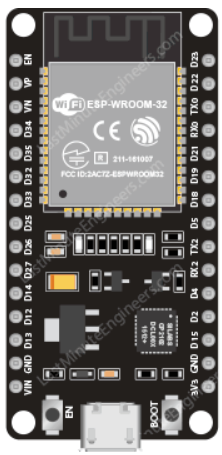
Pin Configuration and Descriptions

The ESP32 has a variety of pins for different functionalities. Below is a table summarizing the key pins:

Pin Name Function Description
GPIO0 General Purpose I/O, Boot Used for boot mode selection during startup.
GPIO2 General Purpose I/O, ADC Can be used as an ADC input or general-purpose pin.
GPIO12 General Purpose I/O, ADC, DAC Supports ADC and DAC functionality.
GPIO13 General Purpose I/O, PWM Can be used for PWM output or general-purpose I/O.
GPIO15 General Purpose I/O, ADC Supports ADC functionality.
EN Enable Resets the chip when pulled low.
3V3 Power Supply Provides 3.3V power to the ESP32.
GND Ground Ground connection.
TX0 UART Transmit Transmit pin for UART0.
RX0 UART Receive Receive pin for UART0.

Note: The ESP32 pinout may vary slightly depending on the specific module or development board (e.g., ESP32-WROOM-32, ESP32-WROVER).

Usage Instructions

How to Use the ESP32 in a Circuit

  1. Powering the ESP32:

    • Connect the 3V3 pin to a 3.3V power source.
    • Ensure the GND pin is connected to the ground of your circuit.
    • Avoid exceeding the maximum voltage of 3.6V to prevent damage.
  2. Programming the ESP32:

    • Use a USB-to-serial adapter or a development board with a built-in USB interface.
    • Install the ESP32 board package in the Arduino IDE or use the Espressif IDF (IoT Development Framework) for advanced programming.
  3. Connecting Peripherals:

    • Use GPIO pins for digital input/output.
    • Connect sensors to ADC pins for analog input.
    • Use I2C, SPI, or UART interfaces for communication with other devices.

Important Considerations and Best Practices

  • Power Supply: Use a stable 3.3V power source with sufficient current (at least 500 mA).
  • Boot Mode: Ensure GPIO0 is pulled low during boot to enter programming mode.
  • Pull-up/Pull-down Resistors: Use appropriate resistors on GPIO pins to avoid floating states.
  • Wi-Fi Interference: Place the ESP32 away from metal objects or other RF sources to ensure reliable Wi-Fi performance.

Example Code for Arduino UNO Integration

Below is an example of how to use the ESP32 with the Arduino IDE to blink an LED connected to GPIO2:

// Example: Blink an LED using ESP32
// Connect an LED to GPIO2 with a 220-ohm resistor in series.

#define LED_PIN 2  // GPIO2 is used for the LED

void setup() {
  pinMode(LED_PIN, OUTPUT);  // Set GPIO2 as an output pin
}

void loop() {
  digitalWrite(LED_PIN, HIGH);  // Turn the LED on
  delay(1000);                  // Wait for 1 second
  digitalWrite(LED_PIN, LOW);   // Turn the LED off
  delay(1000);                  // Wait for 1 second
}

Tip: Ensure the ESP32 is properly connected to your computer and the correct board and port are selected in the Arduino IDE.

Troubleshooting and FAQs

Common Issues and Solutions

  1. ESP32 Not Detected by Computer:

    • Ensure the USB cable is functional and supports data transfer.
    • Install the correct USB-to-serial driver (e.g., CP210x or CH340).
  2. Failed to Upload Code:

    • Check that GPIO0 is pulled low during boot.
    • Verify the correct COM port and board are selected in the Arduino IDE.
    • Press the "EN" (reset) button on the ESP32 board before uploading.
  3. Wi-Fi Connection Issues:

    • Ensure the Wi-Fi credentials (SSID and password) are correct.
    • Check for interference from other devices or weak signal strength.
  4. Random Resets or Instability:

    • Use a stable power supply with sufficient current.
    • Avoid using GPIO pins that are reserved for specific functions (e.g., GPIO6–11 for flash memory).

FAQs

Q: Can the ESP32 operate on 5V?
A: No, the ESP32 operates at 3.3V. Applying 5V to its GPIO pins can damage the chip. Use level shifters if interfacing with 5V devices.

Q: How do I put the ESP32 into deep sleep mode?
A: Use the esp_deep_sleep_start() function in your code. Connect a wake-up source (e.g., GPIO or timer) to wake the ESP32 from deep sleep.

Q: Can I use the ESP32 with Bluetooth and Wi-Fi simultaneously?
A: Yes, the ESP32 supports simultaneous use of Bluetooth and Wi-Fi, but performance may vary depending on the workload.

Q: What is the maximum range of the ESP32's Wi-Fi?
A: The range depends on environmental factors but typically extends up to 100 meters in open space.

By following this documentation, you can effectively use the ESP32 in your projects and troubleshoot common issues.