
How to Use TRANSISTOR_PNP: Examples, Pinouts, and Specs

 Design with TRANSISTOR_PNP in Cirkit Designer
Introduction
A PNP transistor is a type of bipolar junction transistor (BJT) that allows current to flow from the emitter to the collector when a small current is applied to the base. Unlike an NPN transistor, the PNP transistor is activated when the base is pulled to a lower voltage than the emitter. This makes it ideal for applications where the control signal is at a lower potential than the emitter.
Explore Projects Built with TRANSISTOR_PNP
 Open Project in Cirkit Designer
 Open Project in Cirkit Designer
 Open Project in Cirkit Designer
 Open Project in Cirkit Designer
Explore Projects Built with TRANSISTOR_PNP
Open Project in Cirkit DesignerOpen Project in Cirkit DesignerOpen Project in Cirkit DesignerOpen Project in Cirkit DesignerCommon Applications and Use Cases
- Signal amplification in analog circuits
- Switching applications in low-power circuits
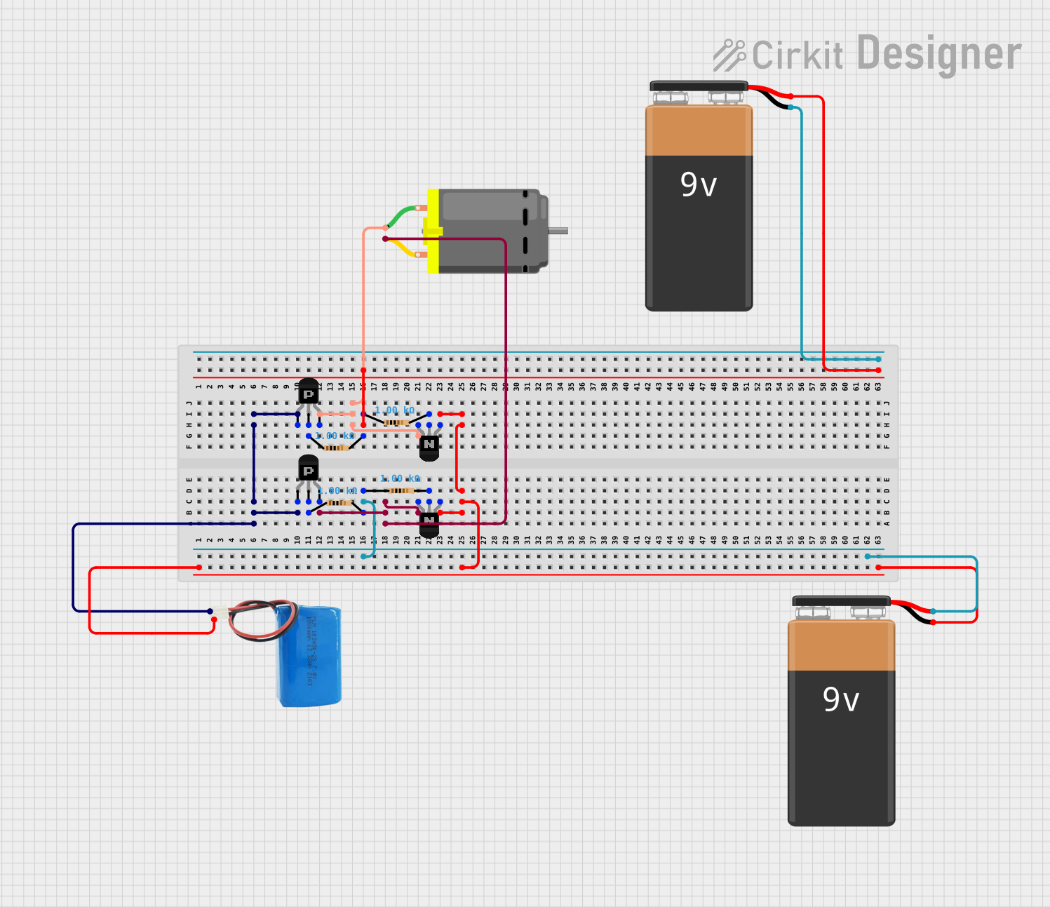
- Used in H-bridge motor drivers
- Current regulation in power supplies
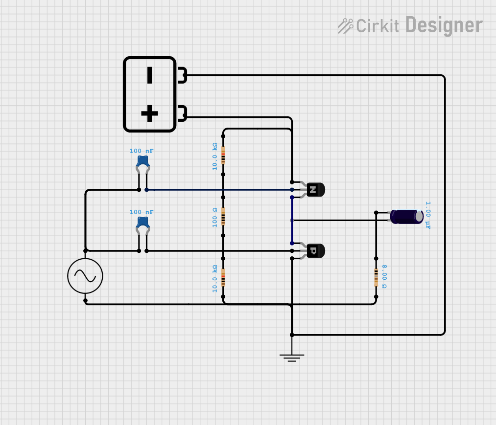
- Complementary pair configurations with NPN transistors
Technical Specifications
Key Technical Details
- Type: Bipolar Junction Transistor (PNP)
- Polarity: PNP
- Voltage Ratings:
- Collector-Emitter Voltage (VCE): Typically 20V to 100V (varies by model)
- Base-Emitter Voltage (VBE): Typically -0.7V to -1.0V
- Current Ratings:
- Maximum Collector Current (IC): Typically 100mA to 10A (varies by model)
- Power Dissipation: Typically 500mW to 2W
- Gain (hFE): Typically 100 to 300
- Package Types: TO-92, TO-220, SOT-23, etc.
Pin Configuration and Descriptions
Below is the pin configuration for a common PNP transistor in a TO-92 package:
| Pin Number | Name | Description |
|---|---|---|
| 1 | Emitter | Current flows out of this terminal |
| 2 | Base | Controls the transistor's operation |
| 3 | Collector | Current flows into this terminal |
For other package types, refer to the specific datasheet of the PNP transistor being used.
Usage Instructions
How to Use the Component in a Circuit
Biasing the Transistor:
- To turn the PNP transistor ON, the base voltage must be lower than the emitter voltage (typically by 0.7V for silicon transistors).
- Connect the emitter to the positive voltage supply.
- Apply a small current to the base through a resistor to control the transistor.
Switching Applications:
- Use the PNP transistor as a high-side switch by connecting the load between the collector and ground.
- When the base is pulled low, the transistor conducts, allowing current to flow through the load.
Amplification Applications:
- Use the transistor in a common-emitter configuration for signal amplification.
- Ensure proper biasing with resistors to set the operating point.
Important Considerations and Best Practices
- Always check the maximum voltage and current ratings of the transistor to avoid damage.
- Use a base resistor to limit the base current and prevent overdriving the transistor.
- Ensure proper heat dissipation if the transistor is used in high-power applications.
- For switching applications, ensure the base voltage is sufficiently lower than the emitter voltage to fully saturate the transistor.
Example: Using a PNP Transistor with Arduino UNO
Below is an example of using a PNP transistor to control an LED with an Arduino UNO:
// Define the pin connected to the base of the PNP transistor
const int transistorBasePin = 9;
// Define the pin connected to the LED (via the transistor's collector)
const int ledPin = 13;

void setup() {
  pinMode(transistorBasePin, OUTPUT); // Set the transistor base pin as output
  pinMode(ledPin, OUTPUT);            // Set the LED pin as output
}

void loop() {
  // Turn the LED ON by pulling the transistor base LOW
  digitalWrite(transistorBasePin, LOW);
  delay(1000); // Keep the LED ON for 1 second

  // Turn the LED OFF by pulling the transistor base HIGH
  digitalWrite(transistorBasePin, HIGH);
  delay(1000); // Keep the LED OFF for 1 second
}
Note:
- A resistor (e.g., 1kΩ) should be placed between the Arduino pin and the transistor base to limit the base current.
- The emitter of the PNP transistor should be connected to the positive voltage supply (e.g., 5V), and the collector should be connected to the LED and a current-limiting resistor.
Troubleshooting and FAQs
Common Issues and Solutions
Transistor Not Turning ON:
- Ensure the base voltage is sufficiently lower than the emitter voltage (by at least 0.7V for silicon transistors).
- Check the base resistor value; it may be too high, limiting the base current.
Excessive Heat:
- Verify that the transistor is not exceeding its maximum current or power dissipation ratings.
- Use a heatsink if necessary for high-power applications.
No Current Flow Through the Load:
- Check the polarity of the connections (emitter, base, and collector).
- Ensure the load is properly connected between the collector and ground.
Arduino Not Controlling the Transistor:
- Confirm that the Arduino pin is configured as an output.
- Verify the base resistor value and ensure it allows sufficient current to flow into the base.
FAQs
Q1: Can I use a PNP transistor in place of an NPN transistor?
A1: No, PNP and NPN transistors have opposite polarities and require different biasing. However, they can be used together in complementary configurations.
Q2: What happens if I exceed the maximum voltage or current ratings?
A2: Exceeding the ratings can permanently damage the transistor. Always operate within the specified limits.
Q3: How do I calculate the base resistor value?
A3: Use the formula:
[
R_b = \frac{V_{in} - V_{BE}}{I_b}
]
Where (V_{in}) is the control voltage, (V_{BE}) is the base-emitter voltage (typically 0.7V), and (I_b) is the required base current ((I_b = I_c / h_{FE})).
By following this documentation, you can effectively use a PNP transistor in your electronic projects!