
How to Use IDG500: Examples, Pinouts, and Specs
 Design with IDG500 in Cirkit Designer
Introduction
The IDG500 is a high-performance inertial measurement unit (IMU) designed to provide precise angular rate measurements. This dual-axis gyroscope is capable of detecting rotational motion with high accuracy, making it an essential component in applications requiring precise motion sensing. The IDG500 is widely used in navigation systems, stabilization platforms, and motion tracking solutions across industries such as aerospace, robotics, and consumer electronics.
Explore Projects Built with IDG500
 Open Project in Cirkit Designer
 Open Project in Cirkit Designer
 Open Project in Cirkit Designer
 Open Project in Cirkit Designer
Explore Projects Built with IDG500
Open Project in Cirkit DesignerOpen Project in Cirkit DesignerOpen Project in Cirkit DesignerOpen Project in Cirkit DesignerCommon Applications:
- Navigation systems for drones and autonomous vehicles
- Stabilization of cameras and gimbals
- Motion tracking in robotics and wearable devices
- Gaming controllers and virtual reality systems
Technical Specifications
The IDG500 is designed to deliver reliable performance under a variety of conditions. Below are its key technical specifications:
| Parameter | Value |
|---|---|
| Supply Voltage | 2.7V to 3.6V |
| Operating Current | 6.5 mA (typical) |
| Measurement Range | ±500°/s |
| Sensitivity | 2.0 mV/°/s |
| Bandwidth | 140 Hz |
| Operating Temperature | -40°C to +85°C |
| Output Type | Analog voltage |
| Package Type | LGA-16 (4 mm x 4 mm) |
Pin Configuration
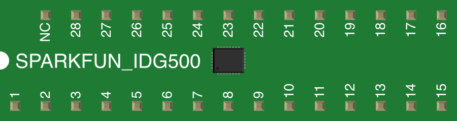
The IDG500 features a 16-pin layout. Below is the pin configuration and description:
| Pin Number | Pin Name | Description |
|---|---|---|
| 1 | VDD | Power supply input (2.7V to 3.6V) |
| 2 | GND | Ground |
| 3 | XOUT | X-axis angular rate output (analog voltage) |
| 4 | YOUT | Y-axis angular rate output (analog voltage) |
| 5 | ST1 | Self-test input for X-axis |
| 6 | ST2 | Self-test input for Y-axis |
| 7 | NC | Not connected |
| 8 | NC | Not connected |
| 9 | VREF | Reference voltage output |
| 10 | C1P | External capacitor connection for charge pump |
| 11 | C1N | External capacitor connection for charge pump |
| 12 | C2P | External capacitor connection for charge pump |
| 13 | C2N | External capacitor connection for charge pump |
| 14 | NC | Not connected |
| 15 | NC | Not connected |
| 16 | NC | Not connected |
Usage Instructions
How to Use the IDG500 in a Circuit
- Power Supply: Connect the VDD pin to a stable power source (2.7V to 3.6V) and the GND pin to ground.
- Output Signals: The XOUT and YOUT pins provide analog voltage proportional to the angular rate. These outputs can be connected to an ADC (Analog-to-Digital Converter) for digital processing.
- Reference Voltage: Use the VREF pin as a reference for the ADC to ensure accurate measurements.
- External Capacitors: Connect appropriate capacitors to the charge pump pins (C1P, C1N, C2P, C2N) as specified in the datasheet to ensure proper operation.
- Self-Test: Use the ST1 and ST2 pins to perform self-tests on the X and Y axes, respectively.
Important Considerations:
- Filtering: Add low-pass filters to the XOUT and YOUT pins to reduce noise and improve signal quality.
- Mounting: Ensure the component is securely mounted to minimize vibrations that could affect measurements.
- Temperature Compensation: Implement temperature compensation in your system to account for drift due to temperature changes.
- Calibration: Perform calibration to eliminate bias and scale factor errors for accurate measurements.
Example: Connecting IDG500 to Arduino UNO
Below is an example of how to interface the IDG500 with an Arduino UNO to read angular rate data:
// Define analog input pins for X and Y outputs
const int xOutPin = A0; // XOUT connected to A0
const int yOutPin = A1; // YOUT connected to A1
const int vRefPin = A2; // VREF connected to A2

void setup() {
  Serial.begin(9600); // Initialize serial communication
  pinMode(xOutPin, INPUT); // Set XOUT pin as input
  pinMode(yOutPin, INPUT); // Set YOUT pin as input
  pinMode(vRefPin, INPUT); // Set VREF pin as input
}

void loop() {
  // Read analog values from the gyroscope
  int xRaw = analogRead(xOutPin);
  int yRaw = analogRead(yOutPin);
  int vRef = analogRead(vRefPin);

  // Convert raw values to angular rate (°/s)
  float xRate = (xRaw - vRef) * (500.0 / 1023.0); // Scale factor for ±500°/s
  float yRate = (yRaw - vRef) * (500.0 / 1023.0);

  // Print angular rate to the serial monitor
  Serial.print("X-Axis Rate: ");
  Serial.print(xRate);
  Serial.print(" °/s, Y-Axis Rate: ");
  Serial.print(yRate);
  Serial.println(" °/s");

  delay(100); // Delay for stability
}
Notes:
- Ensure the VREF pin is connected to the Arduino for accurate ADC readings.
- Use appropriate scaling factors based on the ADC resolution and gyroscope sensitivity.
Troubleshooting and FAQs
Common Issues:
No Output Signal:
- Cause: Incorrect power supply or loose connections.
- Solution: Verify the VDD and GND connections and ensure the supply voltage is within the specified range.
High Noise in Output:
- Cause: Lack of filtering or external interference.
- Solution: Add low-pass filters to the XOUT and YOUT pins and minimize external noise sources.
Drift in Measurements:
- Cause: Temperature variations or lack of calibration.
- Solution: Implement temperature compensation and perform regular calibration.
Self-Test Fails:
- Cause: Incorrect self-test procedure or damaged component.
- Solution: Verify the self-test pin connections and consult the datasheet for proper self-test procedures.
FAQs:
Q1: Can the IDG500 measure angular rates beyond ±500°/s?
A1: No, the IDG500 is designed for a maximum range of ±500°/s. Exceeding this range may result in inaccurate readings or damage to the component.
Q2: Is the IDG500 compatible with 5V systems?
A2: The IDG500 operates at 2.7V to 3.6V. Use a voltage regulator or level shifter to interface with 5V systems.
Q3: How do I reduce noise in the output signal?
A3: Use low-pass filters on the output pins and ensure proper grounding to minimize noise.
Q4: Can I use the IDG500 for 3D motion tracking?
A4: The IDG500 provides angular rate measurements for two axes (X and Y). For 3D motion tracking, you will need an additional sensor for the Z-axis.