How to Use FPC Adapter: Examples, Pinouts, and Specs
Introduction
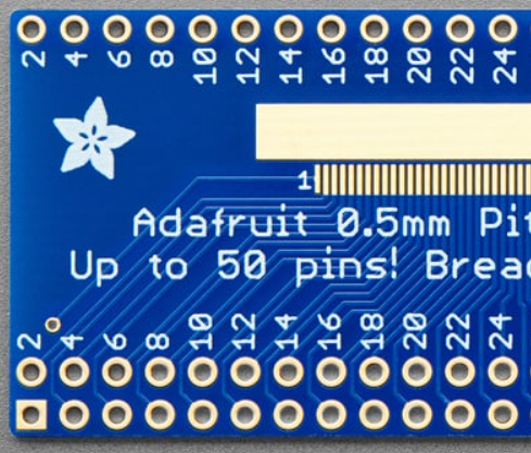
The Adafruit 50-pin 0.5 mm pitch FPC Adapter is a versatile component designed to facilitate the connection of Flexible Printed Circuits (FPCs) to other circuit boards or components. This adapter is particularly useful in compact and flexible electronic designs, where space constraints and the need for reliable connections are critical. It provides a simple and effective way to interface FPCs with standard PCB layouts, making it an essential tool for prototyping and development.
Explore Projects Built with FPC Adapter


Explore Projects Built with FPC Adapter
Common Applications and Use Cases
- Connecting FPCs in consumer electronics, such as smartphones, tablets, and cameras.
- Prototyping and testing FPC-based designs.
- Interfacing LCD displays, touch panels, or other FPC-based modules with microcontrollers or development boards.
- Repairing or replacing damaged FPC connectors in existing devices.
Technical Specifications
The following table outlines the key technical details of the Adafruit 50-pin 0.5 mm pitch FPC Adapter:
| Specification | Details |
|---|---|
| Manufacturer | Adafruit |
| Part ID | 50-pin 0.5 mm pitch FPC Adapter |
| Number of Pins | 50 |
| Pitch | 0.5 mm |
| Connector Type | FPC/FFC (Flexible Printed Circuit/Flexible Flat Cable) |
| Dimensions | 30 mm x 15 mm |
| Material | PCB with gold-plated contacts |
| Operating Temperature | -40°C to 85°C |
Pin Configuration and Descriptions
The FPC adapter features a 50-pin connector with a 0.5 mm pitch. The pinout is straightforward, with each pin corresponding to a 1:1 connection between the FPC and the breakout pins on the adapter. Below is a general description of the pin configuration:
| Pin Number | Description |
|---|---|
| 1-50 | Signal lines for FPC connection |
Note: The specific signal mapping depends on the FPC or device being connected. Refer to the datasheet of the FPC or module for detailed pin assignments.
Usage Instructions
How to Use the FPC Adapter in a Circuit
- Prepare the FPC Cable: Ensure the FPC cable is clean and free of damage. Align the cable with the connector on the adapter.
- Insert the FPC Cable: Gently lift the locking tab on the FPC connector, insert the cable with the exposed contacts facing down, and secure the tab.
- Connect to a Circuit: Use the breakout pins on the adapter to connect the FPC to your circuit. Solder wires or use jumper cables as needed.
- Verify Connections: Double-check all connections to ensure proper alignment and avoid short circuits.
Important Considerations and Best Practices
- Handle with Care: The FPC adapter and cable are delicate. Avoid applying excessive force when inserting or removing the cable.
- Check Compatibility: Ensure the FPC cable matches the adapter's specifications (50 pins, 0.5 mm pitch).
- Avoid Overheating: When soldering, use a low-temperature soldering iron to prevent damage to the adapter or FPC.
- Secure Connections: Use tape or a clamp to hold the FPC cable in place if the connection is prone to movement.
Example: Connecting to an Arduino UNO
The FPC adapter can be used to interface an FPC-based LCD display with an Arduino UNO. Below is an example code snippet for initializing a hypothetical LCD module:
#include <Wire.h> // Include the Wire library for I2C communication

// Define the I2C address of the LCD module
#define LCD_I2C_ADDRESS 0x27

void setup() {
  Wire.begin(); // Initialize I2C communication
  Serial.begin(9600); // Start serial communication for debugging

  // Send initialization commands to the LCD
  Wire.beginTransmission(LCD_I2C_ADDRESS);
  Wire.write(0x80); // Example command to initialize the LCD
  Wire.endTransmission();

  Serial.println("LCD initialized successfully.");
}

void loop() {
  // Example: Send data to the LCD
  Wire.beginTransmission(LCD_I2C_ADDRESS);
  Wire.write("Hello, World!"); // Display text on the LCD
  Wire.endTransmission();

  delay(1000); // Wait for 1 second
}
Note: The above code is a generic example. Refer to the datasheet of your specific FPC-based module for the correct initialization sequence and commands.
Troubleshooting and FAQs
Common Issues Users Might Face
FPC Cable Not Secured Properly:
- Symptom: The circuit does not work, or the connected module is unresponsive.
- Solution: Ensure the FPC cable is fully inserted and the locking tab is securely closed.
Incorrect Pin Mapping:
- Symptom: Signals are not transmitted correctly.
- Solution: Verify the pinout of the FPC and ensure it matches the connections on the adapter.
Damaged FPC Cable or Adapter:
- Symptom: Intermittent or no connection.
- Solution: Inspect the FPC cable and adapter for physical damage. Replace if necessary.
Overheating During Soldering:
- Symptom: The adapter or FPC connector is deformed.
- Solution: Use a soldering iron with temperature control and avoid prolonged heating.
Solutions and Tips for Troubleshooting
- Use a multimeter to check for continuity between the FPC cable and the breakout pins.
- If the connected module does not work, test it independently to rule out issues with the module itself.
- For high-frequency signals, ensure the FPC cable is properly shielded to minimize interference.
By following this documentation, users can effectively utilize the Adafruit 50-pin 0.5 mm pitch FPC Adapter in their projects, ensuring reliable and efficient connections for FPC-based designs.