How to Use relay 2 chanel 5v: Examples, Pinouts, and Specs
Introduction
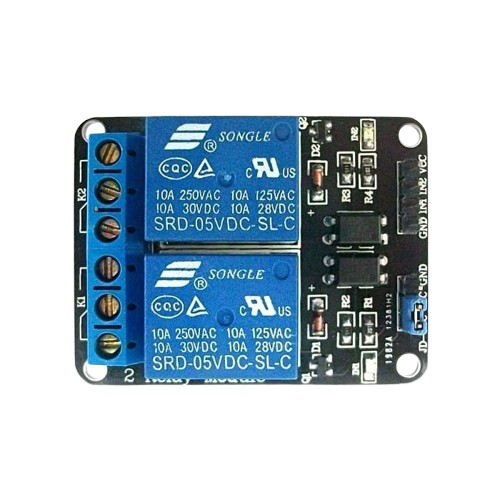
The 2-channel relay module is an electronic component designed to control two independent circuits using a single input signal. Operating at 5V, this module is ideal for switching high-power devices such as motors, lights, and appliances while isolating the control circuit from the load. It is widely used in automation, home control systems, and IoT projects due to its reliability and ease of integration.
Explore Projects Built with relay 2 chanel 5v


Explore Projects Built with relay 2 chanel 5v
Common Applications
- Home automation (e.g., controlling lights or fans)
- Industrial control systems
- IoT projects for remote device control
- Robotics and motor control
- Safety systems requiring electrical isolation
Technical Specifications
Key Technical Details
| Parameter | Value |
|---|---|
| Operating Voltage | 5V DC |
| Trigger Voltage | 3.3V to 5V DC |
| Maximum Load Voltage | 250V AC / 30V DC |
| Maximum Load Current | 10A |
| Channels | 2 |
| Isolation | Optocoupler-based isolation |
| Dimensions | ~50mm x 40mm x 18mm |
| Weight | ~30g |
Pin Configuration and Descriptions
Input Pins
| Pin Name | Description |
|---|---|
| VCC | Connect to 5V DC power supply. |
| GND | Connect to ground (0V). |
| IN1 | Control signal for Relay 1. A HIGH signal activates the relay. |
| IN2 | Control signal for Relay 2. A HIGH signal activates the relay. |
Output Terminals (for each relay)
| Terminal Name | Description |
|---|---|
| COM | Common terminal for the relay. Connect to the power source or load. |
| NO | Normally Open terminal. Connect to the load for switching when active. |
| NC | Normally Closed terminal. Connect to the load for default connection. |
Usage Instructions
How to Use the Component in a Circuit
- Power the Module: Connect the VCC pin to a 5V DC power supply and the GND pin to ground.
- Control Signals: Use a microcontroller (e.g., Arduino UNO) or other control circuits to send HIGH/LOW signals to the IN1 and IN2 pins to activate or deactivate the relays.
- Connect the Load:
- For devices that should be OFF by default, connect them between the COM and NO terminals.
- For devices that should be ON by default, connect them between the COM and NC terminals.
- Isolation: Ensure the control circuit and load circuit are electrically isolated to prevent damage.
Important Considerations and Best Practices
- Power Supply: Ensure the module is powered with a stable 5V DC supply to avoid erratic behavior.
- Load Ratings: Do not exceed the maximum voltage (250V AC / 30V DC) or current (10A) ratings of the relay.
- Flyback Diodes: If controlling inductive loads (e.g., motors), use flyback diodes across the load to protect the relay from voltage spikes.
- Signal Voltage: Ensure the control signal voltage matches the relay's trigger voltage (3.3V to 5V).
- Mounting: Secure the module in a well-ventilated area to prevent overheating.
Example: Connecting to an Arduino UNO
Below is an example of how to control the 2-channel relay module using an Arduino UNO.
Circuit Connections
- Connect the relay module's VCC to the Arduino's 5V pin.
- Connect the relay module's GND to the Arduino's GND pin.
- Connect IN1 to Arduino digital pin 7.
- Connect IN2 to Arduino digital pin 8.
- Connect the load (e.g., a light bulb) to the relay's COM and NO terminals.
Arduino Code
// Define the relay control pins
const int relay1 = 7; // Relay 1 connected to digital pin 7
const int relay2 = 8; // Relay 2 connected to digital pin 8

void setup() {
  // Set relay pins as outputs
  pinMode(relay1, OUTPUT);
  pinMode(relay2, OUTPUT);

  // Initialize relays to OFF state
  digitalWrite(relay1, LOW); // Relay 1 OFF
  digitalWrite(relay2, LOW); // Relay 2 OFF
}

void loop() {
  // Turn Relay 1 ON and Relay 2 OFF
  digitalWrite(relay1, HIGH); // Relay 1 ON
  digitalWrite(relay2, LOW);  // Relay 2 OFF
  delay(2000); // Wait for 2 seconds

  // Turn Relay 1 OFF and Relay 2 ON
  digitalWrite(relay1, LOW);  // Relay 1 OFF
  digitalWrite(relay2, HIGH); // Relay 2 ON
  delay(2000); // Wait for 2 seconds
}
Troubleshooting and FAQs
Common Issues and Solutions
Relays Not Activating:
- Ensure the VCC and GND pins are properly connected to a 5V power supply.
- Verify that the control signal voltage (IN1/IN2) is within the acceptable range (3.3V to 5V).
- Check for loose or incorrect wiring.
Erratic Behavior:
- Use a stable power supply to avoid voltage fluctuations.
- Ensure proper grounding between the relay module and the control circuit.
Load Not Switching:
- Verify the load connections to the COM, NO, and NC terminals.
- Ensure the load does not exceed the relay's voltage and current ratings.
Overheating:
- Avoid exceeding the relay's maximum load ratings.
- Ensure adequate ventilation around the module.
FAQs
Q: Can I use this module with a 3.3V microcontroller?
A: Yes, the relay module can be triggered with a 3.3V control signal, but ensure the VCC pin is powered with 5V.
Q: Can I control DC loads with this relay?
A: Yes, the relay supports DC loads up to 30V and 10A.
Q: Is the relay module safe for high-voltage applications?
A: Yes, the module is designed for high-voltage applications (up to 250V AC), but proper precautions must be taken to ensure safety.
Q: Can I use both NO and NC terminals simultaneously?
A: No, only one terminal (NO or NC) should be connected to the load at a time, depending on the desired behavior.