How to Use MX1508 DC Motor Driver: Examples, Pinouts, and Specs
Introduction
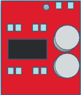
The MX1508 DC Motor Driver is a versatile and compact integrated circuit (IC) capable of controlling the direction and speed of two DC motors independently. It operates as a dual H-bridge motor driver, which means it can drive two motors in both forward and reverse directions. This component is commonly used in robotics, small electric vehicles, and automation projects where precise motor control is required.
Explore Projects Built with MX1508 DC Motor Driver
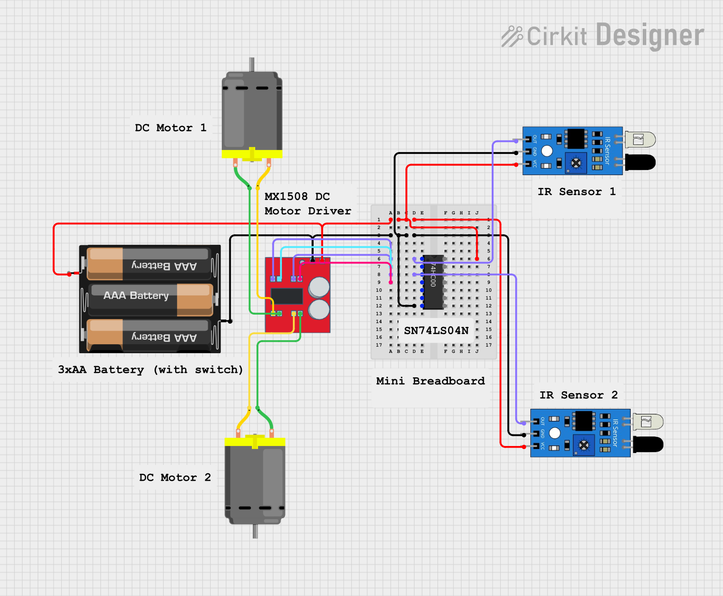
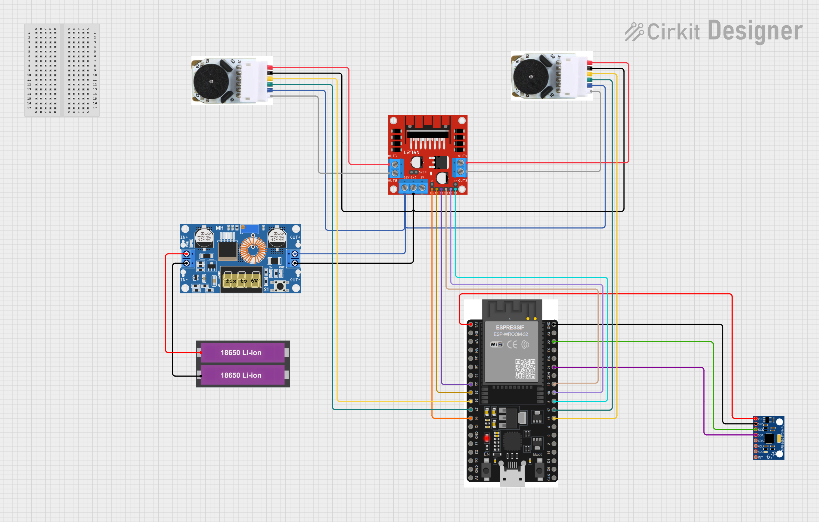

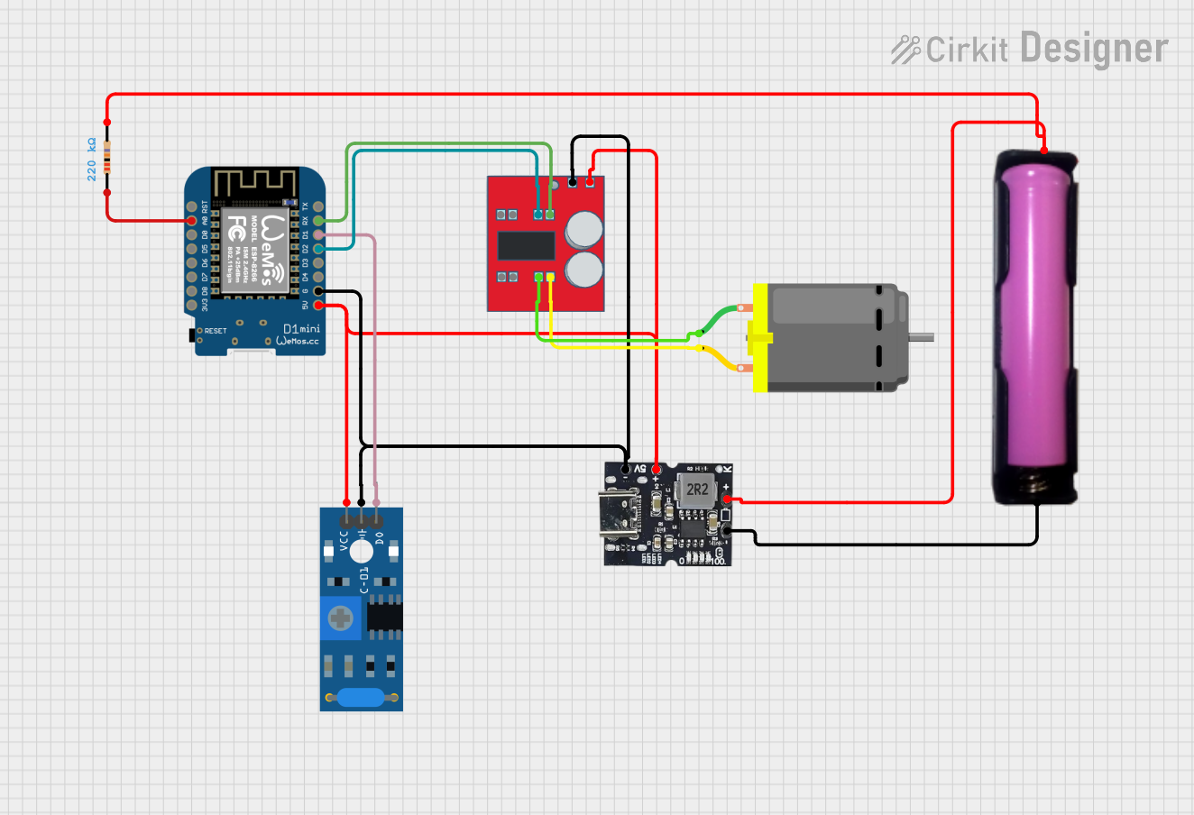
Explore Projects Built with MX1508 DC Motor Driver
Common Applications and Use Cases
- Robotics
- Automated guided vehicles (AGVs)
- Small electric cars or boats
- DIY electronic projects
- Educational platforms for learning motor control
Technical Specifications
Key Technical Details
- Operating Voltage: 2V to 10V
- Continuous Output Current: 1.5A (maximum peak current 2.5A)
- Standby Current: <0.1uA
- Logic Voltage: 2V to 5.5V
- Control Method: TTL/CMOS logic level compatible
Pin Configuration and Descriptions
| Pin Number | Pin Name | Description |
|---|---|---|
| 1 | OUT1 | Motor A output 1 |
| 2 | OUT2 | Motor A output 2 |
| 3 | VCC | Motor power supply (2V to 10V) |
| 4 | GND | Ground |
| 5 | IN1 | Control input for motor A direction |
| 6 | IN2 | Control input for motor A direction |
| 7 | IN3 | Control input for motor B direction |
| 8 | IN4 | Control input for motor B direction |
| 9 | OUT3 | Motor B output 1 |
| 10 | OUT4 | Motor B output 2 |
| 11 | VCC | Logic power supply (2V to 5.5V) |
| 12 | GND | Ground |
Usage Instructions
How to Use the Component in a Circuit
- Connect the motor power supply to the VCC (pin 3) and GND (pin 4).
- Connect the logic power supply to the VCC (pin 11) and GND (pin 12).
- Connect the control inputs (IN1, IN2 for motor A and IN3, IN4 for motor B) to your microcontroller or control circuit.
- Connect the motor leads to the output pins (OUT1, OUT2 for motor A and OUT3, OUT4 for motor B).
Important Considerations and Best Practices
- Ensure that the power supply voltage does not exceed the maximum rating of 10V.
- Do not exceed the continuous output current rating of 1.5A per channel.
- Use a separate power supply for the motors and logic if noise or interference is a concern.
- Include flyback diodes across the motor terminals to protect the driver from voltage spikes.
- Avoid running the motors at stall current as it may exceed the peak current rating and damage the driver.
Example Code for Arduino UNO
// Define the control pins for Motor A
const int motorAIn1 = 2;
const int motorAIn2 = 3;

// Define the control pins for Motor B
const int motorBIn3 = 4;
const int motorBIn4 = 5;

void setup() {
  // Set all the motor control pins to outputs
  pinMode(motorAIn1, OUTPUT);
  pinMode(motorAIn2, OUTPUT);
  pinMode(motorBIn3, OUTPUT);
  pinMode(motorBIn4, OUTPUT);
}

void loop() {
  // Drive Motor A forward
  digitalWrite(motorAIn1, HIGH);
  digitalWrite(motorAIn2, LOW);

  // Drive Motor B forward
  digitalWrite(motorBIn3, HIGH);
  digitalWrite(motorBIn4, LOW);

  delay(2000); // Run motors for 2 seconds

  // Reverse Motor A
  digitalWrite(motorAIn1, LOW);
  digitalWrite(motorAIn2, HIGH);

  // Reverse Motor B
  digitalWrite(motorBIn3, LOW);
  digitalWrite(motorBIn4, HIGH);

  delay(2000); // Run motors in reverse for 2 seconds
}
Troubleshooting and FAQs
Common Issues Users Might Face
- Motor not running: Check power supply connections and ensure the control inputs are receiving the correct logic signals.
- Overheating: Ensure the current through the motor driver does not exceed 1.5A. Use heat sinks if necessary.
- Erratic behavior: Verify that the logic power supply is stable and within the specified range.
Solutions and Tips for Troubleshooting
- Double-check wiring and connections for any loose or incorrect connections.
- Measure the voltage at the motor driver's power supply pins to ensure it is within the specified range.
- Use a multimeter to check the continuity of the motor and the output pins to ensure there are no open circuits.
FAQs
Q: Can I control the speed of the motors using the MX1508? A: Yes, you can control the speed by applying PWM (Pulse Width Modulation) signals to the control inputs.
Q: What should I do if the motor driver gets hot during operation? A: Ensure that the current is within the safe operating limits and consider adding a heat sink to dissipate heat more effectively.
Q: Can the MX1508 drive stepper motors? A: No, the MX1508 is designed for DC motors and does not have the necessary control for stepper motors.