How to Use MH-Z19D Infrared CO2 Sensor Module: Examples, Pinouts, and Specs
Introduction
The MH-Z19D is a high-precision infrared sensor module manufactured by Zhengzhou Winsen Electronics Technology Co., Ltd. It is designed to measure carbon dioxide (CO2) concentration in the air using non-dispersive infrared (NDIR) technology. This sensor is known for its accuracy, stability, and ease of integration into various electronic systems.
Explore Projects Built with MH-Z19D Infrared CO2 Sensor Module
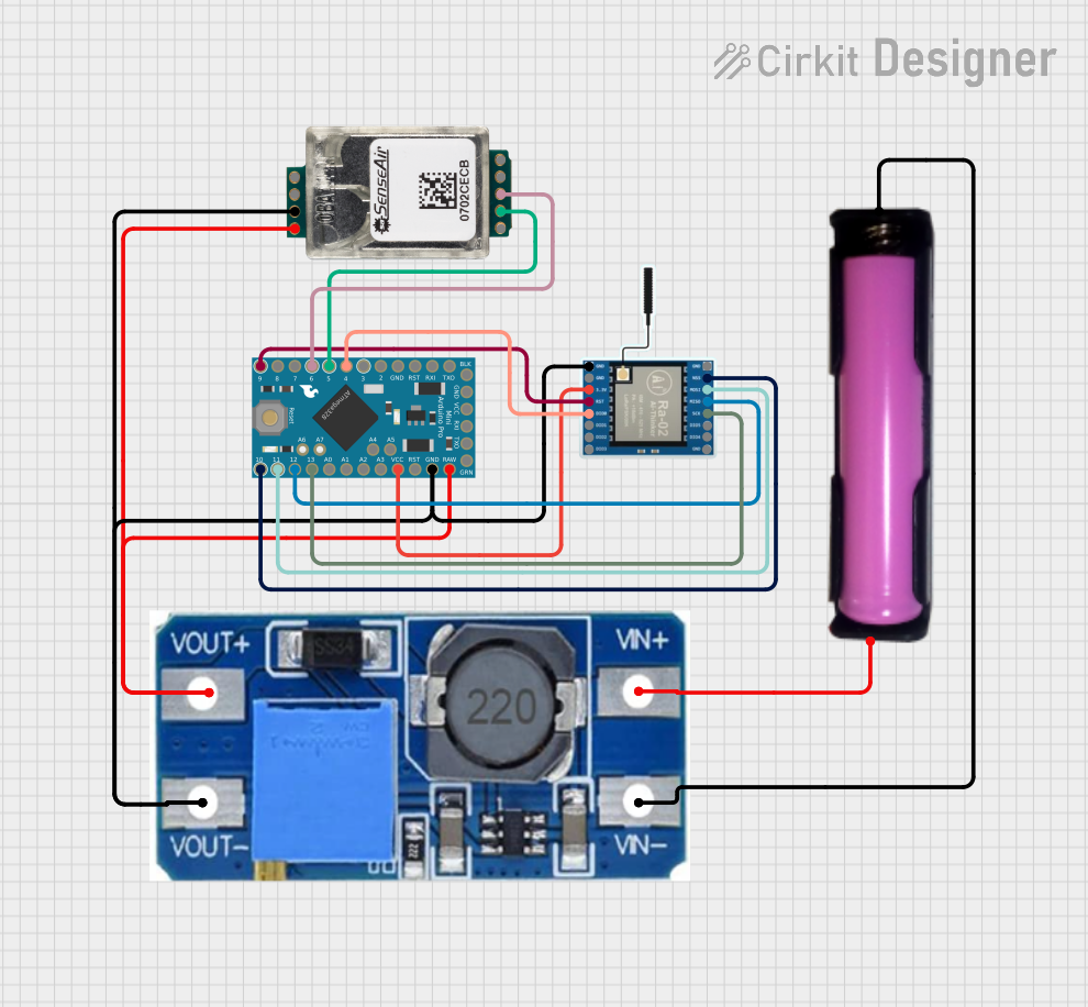
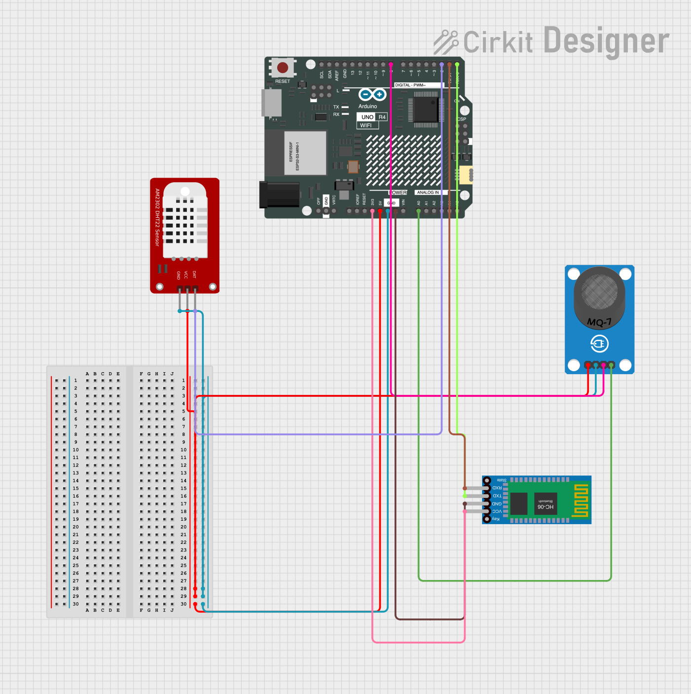

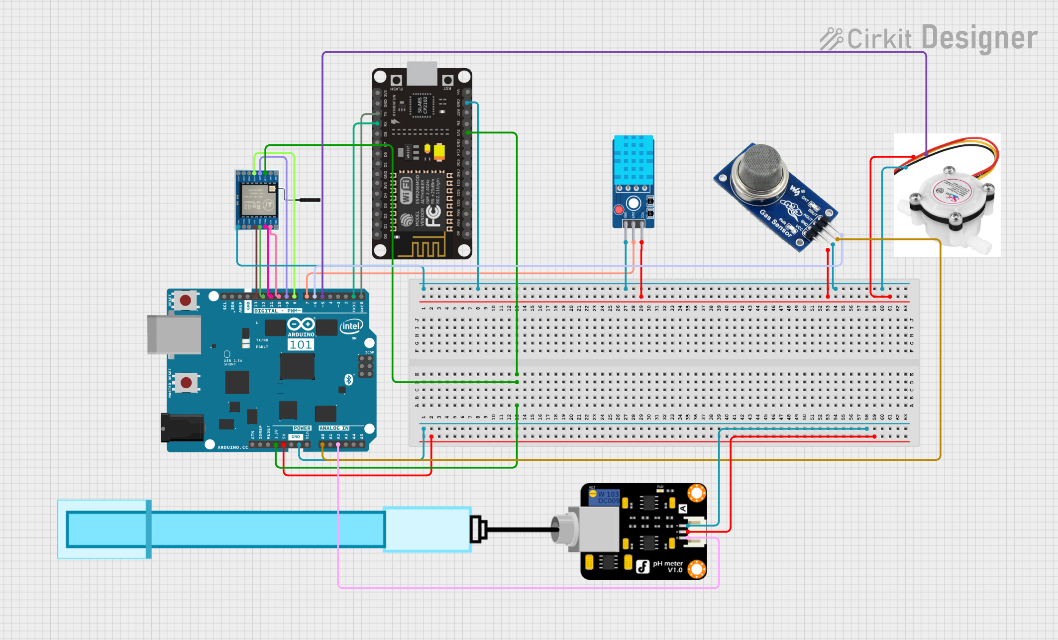
Explore Projects Built with MH-Z19D Infrared CO2 Sensor Module
Common Applications
- Indoor air quality monitoring
- HVAC (Heating, Ventilation, and Air Conditioning) systems
- Greenhouse CO2 monitoring
- Industrial process control
- Smart home and IoT devices
Technical Specifications
The following table outlines the key technical details of the MH-Z19D sensor module:
| Parameter | Value |
|---|---|
| Measurement Range | 0 - 5000 ppm (parts per million) |
| Accuracy | ± (50 ppm + 5% of reading) |
| Response Time (T90) | < 30 seconds |
| Operating Voltage | 4.5V - 5.5V DC |
| Average Current | < 20 mA |
| Output Signal | UART (3.3V TTL) and PWM |
| Operating Temperature | -10°C to 50°C |
| Operating Humidity | 0% - 95% RH (non-condensing) |
| Dimensions | 33 mm × 20 mm × 9 mm |
| Weight | ~5 grams |
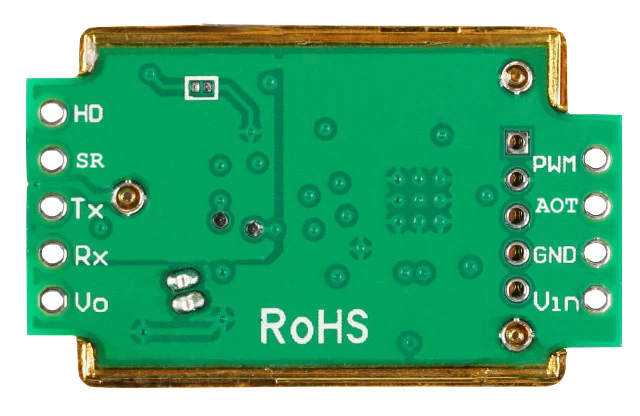
Pin Configuration and Descriptions
The MH-Z19D module has a 7-pin interface. The pinout and descriptions are as follows:
| Pin Number | Pin Name | Description |
|---|---|---|
| 1 | VCC | Power supply input (4.5V - 5.5V DC) |
| 2 | GND | Ground connection |
| 3 | PWM | PWM output for CO2 concentration (optional) |
| 4 | NC | Not connected (leave unconnected) |
| 5 | UART_RX | UART receive pin (3.3V TTL logic) |
| 6 | UART_TX | UART transmit pin (3.3V TTL logic) |
| 7 | HD | Hardware reset pin (active low, optional) |
Usage Instructions
Connecting the MH-Z19D to a Circuit
- Power Supply: Connect the VCC pin to a 5V DC power source and the GND pin to ground.
- UART Communication:
- Connect the UART_TX pin of the sensor to the RX pin of your microcontroller (e.g., Arduino).
- Connect the UART_RX pin of the sensor to the TX pin of your microcontroller.
- PWM Output (Optional): If you prefer to use the PWM output for CO2 readings, connect the PWM pin to a digital input pin on your microcontroller.
- Hardware Reset (Optional): The HD pin can be connected to a GPIO pin for manual reset functionality, but it is not required for normal operation.
Important Considerations
- Warm-Up Time: Allow the sensor to warm up for at least 3 minutes after powering it on to ensure accurate readings.
- Calibration: The MH-Z19D supports automatic baseline correction (ABC) to maintain long-term accuracy. Ensure the sensor is exposed to fresh air periodically for proper calibration.
- Voltage Levels: The UART pins operate at 3.3V TTL logic. If your microcontroller uses 5V logic, use a level shifter to avoid damaging the sensor.
Example Code for Arduino UNO
Below is an example of how to interface the MH-Z19D with an Arduino UNO using UART communication:
#include <SoftwareSerial.h>

// Define RX and TX pins for SoftwareSerial
SoftwareSerial mySerial(10, 11); // RX = Pin 10, TX = Pin 11

byte cmd_get_concentration[] = {0xFF, 0x01, 0x86, 0x00, 0x00, 0x00, 0x00, 0x00, 0x79};
unsigned char response[9];

void setup() {
  Serial.begin(9600);         // Initialize hardware serial for debugging
  mySerial.begin(9600);       // Initialize software serial for MH-Z19D
  Serial.println("MH-Z19D CO2 Sensor Initialized");
}

void loop() {
  // Send command to request CO2 concentration
  mySerial.write(cmd_get_concentration, 9);
  delay(100); // Wait for the sensor to respond

  // Read the response
  if (mySerial.available()) {
    for (int i = 0; i < 9; i++) {
      response[i] = mySerial.read();
    }

    // Check if the response is valid
    if (response[0] == 0xFF && response[1] == 0x86) {
      int high = response[2];
      int low = response[3];
      int ppm = (high << 8) + low; // Combine high and low bytes
      Serial.print("CO2 Concentration: ");
      Serial.print(ppm);
      Serial.println(" ppm");
    } else {
      Serial.println("Invalid response from sensor");
    }
  }

  delay(2000); // Wait 2 seconds before the next reading
}
Notes:
- Replace
10and11inSoftwareSerial mySerial(10, 11)with the pins you want to use for RX and TX on your Arduino. - Ensure the sensor is connected to the correct pins and powered properly.
Troubleshooting and FAQs
Common Issues
No Response from the Sensor
- Cause: Incorrect wiring or insufficient power supply.
- Solution: Double-check the connections and ensure the sensor is receiving 5V DC.
Inaccurate Readings
- Cause: Sensor not warmed up or improperly calibrated.
- Solution: Allow the sensor to warm up for at least 3 minutes. Ensure the sensor is exposed to fresh air periodically for automatic baseline correction.
UART Communication Issues
- Cause: Mismatched baud rate or incorrect RX/TX connections.
- Solution: Verify that the baud rate is set to 9600 and that RX/TX pins are correctly connected.
PWM Output Not Working
- Cause: Incorrect pin configuration or signal interpretation.
- Solution: Ensure the PWM pin is connected to a digital input pin and use appropriate code to read the PWM signal.
FAQs
Q: Can the MH-Z19D measure CO2 concentrations above 5000 ppm?
A: No, the sensor's maximum measurement range is 5000 ppm.Q: How often should I calibrate the sensor?
A: The sensor supports automatic baseline correction (ABC), which calibrates the sensor automatically when exposed to fresh air. Manual calibration is not typically required.Q: Can I use the MH-Z19D with a 3.3V power supply?
A: No, the sensor requires a 4.5V - 5.5V DC power supply for proper operation.Q: Is the sensor suitable for outdoor use?
A: The sensor is designed for indoor use. It may not perform reliably in extreme environmental conditions or high humidity.
By following this documentation, you can effectively integrate the MH-Z19D sensor into your projects and ensure accurate CO2 measurements.