How to Use Contactor: Examples, Pinouts, and Specs
Introduction
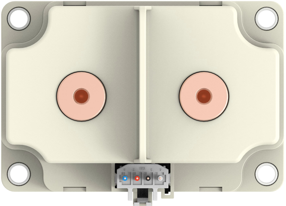
A contactor is an electrically controlled switch designed to handle high-current power circuits. Unlike standard relays, contactors are specifically engineered for applications requiring frequent switching and high current capacity. Manufactured by TE Connectivity, the Contactor Main is a robust and reliable solution for industrial and commercial power control needs.
Explore Projects Built with Contactor


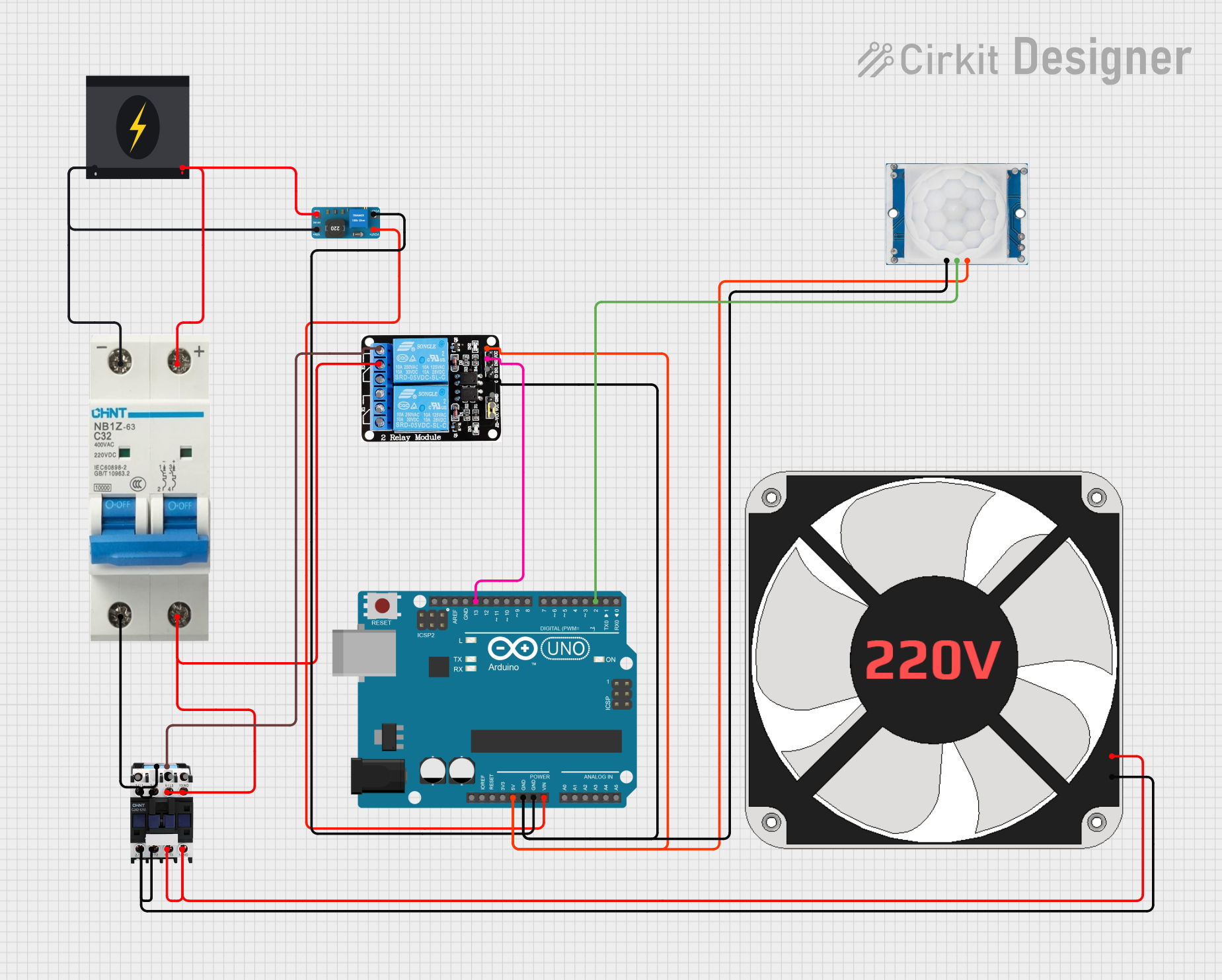
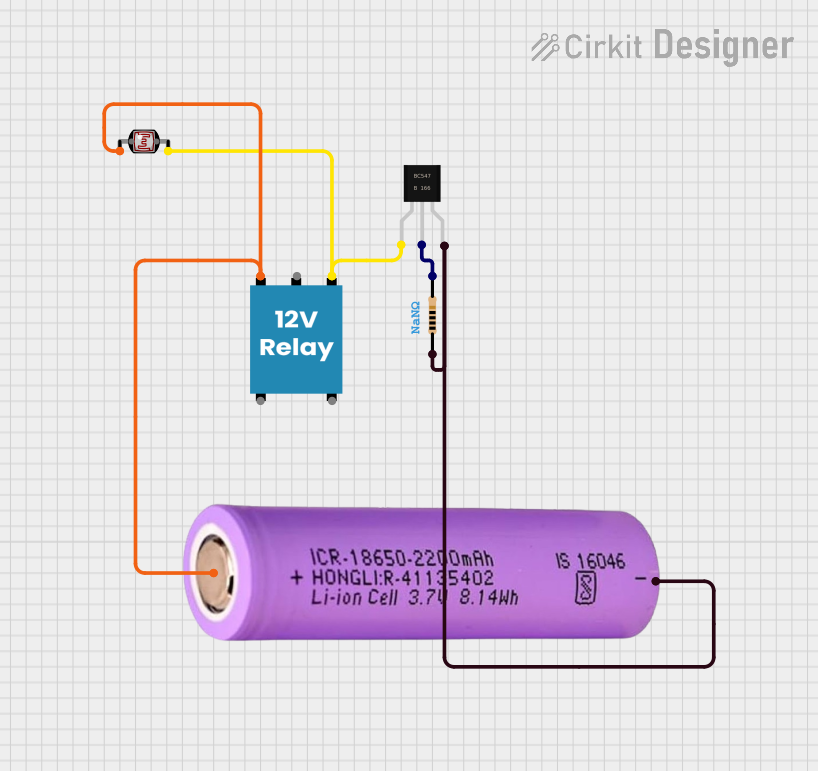
Explore Projects Built with Contactor
Common Applications and Use Cases
- Motor control in industrial machinery
- Lighting control in commercial buildings
- HVAC systems
- Power distribution and automation systems
- Renewable energy systems (e.g., solar inverters)
Technical Specifications
Key Technical Details
- Manufacturer: TE Connectivity
- Part ID: Contactor Main
- Rated Voltage: 24V DC (coil voltage)
- Rated Current: Up to 100A (depending on the model)
- Contact Configuration: Normally Open (NO) or Normally Closed (NC)
- Insulation Voltage: 690V AC
- Operating Temperature Range: -25°C to +70°C
- Mechanical Life: 10 million operations
- Electrical Life: 1 million operations (at rated load)
Pin Configuration and Descriptions
The Contactor Main typically has the following pin configuration:
| Pin Number | Label | Description |
|---|---|---|
| 1 | A1 | Coil positive terminal (24V DC input) |
| 2 | A2 | Coil negative terminal (ground) |
| 3 | L1 | Power input terminal (phase 1) |
| 4 | L2 | Power input terminal (phase 2) |
| 5 | L3 | Power input terminal (phase 3) |
| 6 | T1 | Power output terminal (phase 1) |
| 7 | T2 | Power output terminal (phase 2) |
| 8 | T3 | Power output terminal (phase 3) |
| 9 | Auxiliary NO | Auxiliary contact, Normally Open (used for control or feedback circuits) |
| 10 | Auxiliary NC | Auxiliary contact, Normally Closed (used for control or feedback circuits) |
Usage Instructions
How to Use the Contactor in a Circuit
Power the Coil:
- Connect the coil terminals (A1 and A2) to a 24V DC power source. Ensure proper polarity.
- When the coil is energized, the contactor will close or open the main power circuit, depending on its configuration.
Connect the Power Circuit:
- Connect the input power lines to terminals L1, L2, and L3.
- Connect the load (e.g., motor, lighting system) to terminals T1, T2, and T3.
- Ensure the current and voltage ratings of the contactor match the load requirements.
Use Auxiliary Contacts (Optional):
- Auxiliary contacts (NO and NC) can be used for control or feedback purposes in automation systems.
- For example, connect the NO contact to an indicator light to show when the contactor is active.
Safety Precautions:
- Always disconnect power before wiring or servicing the contactor.
- Use proper insulation and grounding to prevent electrical hazards.
- Verify the contactor's ratings to ensure compatibility with your application.
Arduino UNO Example Code
The Contactor Main can be controlled using an Arduino UNO. Below is an example of how to control the contactor using a digital output pin and a relay module (to handle the 24V DC coil voltage).
// Arduino code to control a contactor using a relay module
const int relayPin = 7; // Digital pin connected to the relay module

void setup() {
  pinMode(relayPin, OUTPUT); // Set the relay pin as an output
  digitalWrite(relayPin, LOW); // Ensure the relay is off at startup
}

void loop() {
  // Turn the contactor ON
  digitalWrite(relayPin, HIGH); // Activate the relay
  delay(5000); // Keep the contactor ON for 5 seconds

  // Turn the contactor OFF
  digitalWrite(relayPin, LOW); // Deactivate the relay
  delay(5000); // Keep the contactor OFF for 5 seconds
}
Note:
- Use a relay module capable of switching 24V DC to control the contactor coil.
- Ensure the Arduino's power supply and the relay module are properly grounded.
Important Considerations and Best Practices
- Voltage Matching: Ensure the coil voltage (24V DC) matches the power supply.
- Load Ratings: Verify that the contactor's current and voltage ratings are suitable for the load.
- Heat Dissipation: Install the contactor in a well-ventilated area to prevent overheating.
- Noise Suppression: Use a snubber circuit or flyback diode across the coil terminals to suppress voltage spikes.
Troubleshooting and FAQs
Common Issues and Solutions
| Issue | Possible Cause | Solution |
|---|---|---|
| Contactor does not activate | Coil not receiving power | Check the power supply and ensure proper connections to A1 and A2 terminals. |
| Contactor buzzes or vibrates | Insufficient coil voltage | Verify the coil voltage is 24V DC and stable. |
| Overheating during operation | Overloaded or poor ventilation | Ensure the load does not exceed the contactor's rated current. Improve airflow. |
| Auxiliary contacts not working | Incorrect wiring or damaged contacts | Verify wiring and test the auxiliary contacts for continuity. |
| Frequent contactor failure | Excessive switching or improper load handling | Use a contactor with higher ratings or reduce switching frequency. |
FAQs
Can the contactor handle DC loads?
- The Contactor Main is primarily designed for AC loads. For DC loads, consult the manufacturer for specific models.
What is the difference between a contactor and a relay?
- A contactor is designed for high-current applications, while a relay is typically used for low-current control circuits.
How do I know if the contactor is working?
- You can check the auxiliary NO contact for continuity when the coil is energized. Additionally, listen for a clicking sound when the contactor operates.
Can I use the contactor in outdoor environments?
- The Contactor Main is not weatherproof. Use an appropriate enclosure for outdoor applications.
By following this documentation, you can effectively integrate the Contactor Main into your power control systems while ensuring safe and reliable operation.