How to Use Two Channel Relay: Examples, Pinouts, and Specs
Introduction
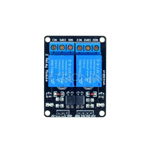
The Two Channel Relay is a versatile electronic module designed to control two independent circuits using low voltage control signals. It acts as an electrically operated switch, allowing users to control high voltage devices such as lights, fans, or appliances with low voltage microcontrollers like Arduino, Raspberry Pi, or other logic-level devices.
This module is widely used in home automation, industrial control systems, and robotics, where safe and efficient switching of high-power devices is required.
Explore Projects Built with Two Channel Relay


Explore Projects Built with Two Channel Relay
Common Applications
- Home automation systems (e.g., controlling lights or appliances)
- Industrial equipment control
- Robotics and motor control
- IoT (Internet of Things) projects
- Safety systems requiring electrical isolation
Technical Specifications
The Two Channel Relay module is designed to handle a wide range of voltages and currents, making it suitable for various applications. Below are the key technical details:
General Specifications
- Relay Type: Electromechanical
- Number of Channels: 2
- Control Voltage: 3.3V to 5V (logic level)
- Switching Voltage (AC): Up to 250V AC
- Switching Voltage (DC): Up to 30V DC
- Switching Current: Up to 10A
- Trigger Mode: Active Low
- Isolation: Optocoupler isolation for safe operation
- Dimensions: ~50mm x 40mm x 20mm
Pin Configuration and Descriptions
The Two Channel Relay module has the following pin layout:
Control Pins
| Pin Name | Description |
|---|---|
| VCC | Power supply for the module (3.3V-5V) |
| GND | Ground connection |
| IN1 | Control signal for Relay 1 (Active Low) |
| IN2 | Control signal for Relay 2 (Active Low) |
Relay Output Terminals
Each relay has three output terminals:
| Terminal | Description |
|---|---|
| NO (Normally Open) | Open circuit when the relay is inactive. Closes when activated. |
| NC (Normally Closed) | Closed circuit when the relay is inactive. Opens when activated. |
| COM (Common) | Common terminal for the relay switching circuit. |
Usage Instructions
How to Use the Two Channel Relay in a Circuit
- Power the Module: Connect the VCC pin to a 5V power source and the GND pin to ground.
- Connect Control Signals: Use a microcontroller (e.g., Arduino) to send control signals to the IN1 and IN2 pins. A LOW signal activates the corresponding relay.
- Connect the Load:
- For each relay, connect the high voltage device to the COM and NO/NC terminals based on your requirements:
- Use NO if you want the device to turn on when the relay is activated.
- Use NC if you want the device to turn off when the relay is activated.
- For each relay, connect the high voltage device to the COM and NO/NC terminals based on your requirements:
- Test the Circuit: Ensure all connections are secure and test the circuit by toggling the control signals.
Important Considerations
- Isolation: The module uses optocouplers to isolate the control circuit from the high voltage circuit, ensuring safety.
- Power Supply: Ensure the power supply to the relay module matches its voltage requirements (3.3V-5V).
- Load Ratings: Do not exceed the relay's maximum voltage and current ratings (250V AC/30V DC, 10A).
- Active Low Trigger: The relay is activated when the control pin is pulled LOW.
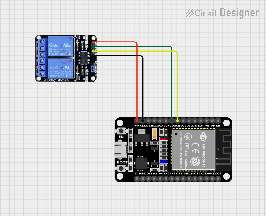
Example: Connecting to an Arduino UNO
Below is an example of how to control the Two Channel Relay using an Arduino UNO:
Circuit Connections
- Connect the VCC pin of the relay module to the 5V pin on the Arduino.
- Connect the GND pin of the relay module to the GND pin on the Arduino.
- Connect IN1 to Arduino digital pin 7.
- Connect IN2 to Arduino digital pin 8.
Arduino Code
// Two Channel Relay Control Example
// This code toggles two relays ON and OFF with a 1-second delay.

#define RELAY1 7  // Define pin 7 for Relay 1 control
#define RELAY2 8  // Define pin 8 for Relay 2 control

void setup() {
  pinMode(RELAY1, OUTPUT); // Set Relay 1 pin as output
  pinMode(RELAY2, OUTPUT); // Set Relay 2 pin as output

  // Initialize relays to OFF state (HIGH because it's active LOW)
  digitalWrite(RELAY1, HIGH);
  digitalWrite(RELAY2, HIGH);
}

void loop() {
  // Turn Relay 1 ON and Relay 2 OFF
  digitalWrite(RELAY1, LOW);  // Activate Relay 1
  digitalWrite(RELAY2, HIGH); // Deactivate Relay 2
  delay(1000);                // Wait for 1 second

  // Turn Relay 1 OFF and Relay 2 ON
  digitalWrite(RELAY1, HIGH); // Deactivate Relay 1
  digitalWrite(RELAY2, LOW);  // Activate Relay 2
  delay(1000);                // Wait for 1 second
}
Troubleshooting and FAQs
Common Issues and Solutions
Relay Not Activating:
- Cause: Insufficient power supply or incorrect wiring.
- Solution: Ensure the VCC pin is connected to a stable 5V source and the GND pin is properly grounded.
Relay Stays ON/OFF Constantly:
- Cause: Incorrect control signal or damaged relay.
- Solution: Verify the control signal logic (active LOW). Test the relay with a direct LOW signal to confirm functionality.
High Voltage Device Not Switching:
- Cause: Incorrect wiring of the load to the relay terminals.
- Solution: Double-check the connections to the COM, NO, and NC terminals.
Arduino Resets When Relay Activates:
- Cause: Voltage spikes or insufficient power supply.
- Solution: Add a flyback diode across the relay coil and ensure the Arduino has a stable power source.
FAQs
Q: Can I use the relay module with a 3.3V microcontroller?
A: Yes, the module supports 3.3V control signals, but ensure the power supply to the relay is sufficient.Q: Is the relay safe for switching high voltage devices?
A: Yes, the relay is designed for high voltage applications, but always follow safety precautions and ensure proper insulation.Q: Can I control both relays independently?
A: Yes, each relay has its own control pin (IN1 and IN2) for independent operation.
By following this documentation, you can safely and effectively use the Two Channel Relay module in your projects.