Cirkit Designer Logo
Cirkit Designer
Your all-in-one circuit design IDE
Home / 
Component Documentation

How to Use ScioSense APC1: Examples, Pinouts, and Specs

Image of ScioSense APC1
Cirkit Designer LogoDesign with ScioSense APC1 in Cirkit Designer

Introduction

The ScioSense APC1 is an advanced air quality sensor designed to monitor various pollutants and environmental parameters. It provides real-time data on air quality, enabling users to make informed decisions regarding health and safety. The APC1 is equipped with high-precision sensing capabilities and is ideal for applications requiring accurate air quality monitoring.

Explore Projects Built with ScioSense APC1

Use Cirkit Designer to design, explore, and prototype these projects online. Some projects support real-time simulation. Click "Open Project" to start designing instantly!
Arduino UNO and BMP085 Based Weather Station with Solar Charging and APC220 Wireless Communication
Image of Vicsat-1: A project utilizing ScioSense APC1 in a practical application
This circuit features an Arduino UNO collecting environmental data from a BMP085 sensor and location data from a GPS module, transmitting it wirelessly via an APC220 module. It is powered by a solar-charged lithium-ion battery system, with a secondary Arduino UNO R4 WiFi and APC220 for potential expansion or separate functionality.
Cirkit Designer LogoOpen Project in Cirkit Designer
ESP32-Based Air Quality Monitoring Station with BMP280, SGP41, and PMS5003 Sensors
Image of indoor-sensors-v6: A project utilizing ScioSense APC1 in a practical application
This circuit is designed for environmental sensing and monitoring, featuring multiple sensors including a BMP280 for barometric pressure and temperature, a SenseAir S8 for CO2 levels, a PMS5003 for particulate matter, and an SGP41 for VOC and NOx levels. These sensors are interfaced with an ESP32 microcontroller, which likely serves as the central processing unit to collect, process, and possibly transmit sensor data. The ESP32 is connected to the sensors using I2C (SDA/SCL lines) and serial communication (RX/TX lines), and it provides power to the sensors (3V3/VIN lines).
Cirkit Designer LogoOpen Project in Cirkit Designer
Wemos S2 Mini Controlled Smart Device with OLED Display, Thermal Printing, and RGB LED Strip
Image of DT NEA - Noah Patel: A project utilizing ScioSense APC1 in a practical application
This circuit features a Wemos S2 Mini microcontroller that controls a WS2812 RGB LED strip and communicates with a 0.96" OLED display and a 58mm mini thermal printer. The ACS712 Current Sensor is interfaced with the microcontroller to monitor current, and power is managed by a CD42 BMS connected to two 18650 Li-ion batteries, with a USB-C PD Trigger Board for power delivery. The circuit is designed for visual output (LED strip, OLED display), printing capabilities, and current sensing, likely for a portable, battery-powered monitoring and display device.
Cirkit Designer LogoOpen Project in Cirkit Designer
Arduino Nano Controlled Smart Relay with APDS-9960 Gesture Sensor
Image of contactless smart switch: A project utilizing ScioSense APC1 in a practical application
This circuit features an Arduino Nano microcontroller interfaced with an Adafruit APDS-9960 sensor and a 2-channel relay module. The APDS-9960 sensor, which is capable of gesture detection, is connected to the Arduino via I2C communication lines (SCL, SDA) and powered by the Arduino's 3.3V output. The relay module is controlled by the Arduino through a digital pin (D7) and is used to switch an AC-powered bulb on and off, with the relay's common (COM) terminal connected to the AC source and the normally open (NO1) terminal connected to the bulb.
Cirkit Designer LogoOpen Project in Cirkit Designer

Explore Projects Built with ScioSense APC1

Use Cirkit Designer to design, explore, and prototype these projects online. Some projects support real-time simulation. Click "Open Project" to start designing instantly!
Image of Vicsat-1: A project utilizing ScioSense APC1 in a practical application
Arduino UNO and BMP085 Based Weather Station with Solar Charging and APC220 Wireless Communication
This circuit features an Arduino UNO collecting environmental data from a BMP085 sensor and location data from a GPS module, transmitting it wirelessly via an APC220 module. It is powered by a solar-charged lithium-ion battery system, with a secondary Arduino UNO R4 WiFi and APC220 for potential expansion or separate functionality.
Cirkit Designer LogoOpen Project in Cirkit Designer
Image of indoor-sensors-v6: A project utilizing ScioSense APC1 in a practical application
ESP32-Based Air Quality Monitoring Station with BMP280, SGP41, and PMS5003 Sensors
This circuit is designed for environmental sensing and monitoring, featuring multiple sensors including a BMP280 for barometric pressure and temperature, a SenseAir S8 for CO2 levels, a PMS5003 for particulate matter, and an SGP41 for VOC and NOx levels. These sensors are interfaced with an ESP32 microcontroller, which likely serves as the central processing unit to collect, process, and possibly transmit sensor data. The ESP32 is connected to the sensors using I2C (SDA/SCL lines) and serial communication (RX/TX lines), and it provides power to the sensors (3V3/VIN lines).
Cirkit Designer LogoOpen Project in Cirkit Designer
Image of DT NEA - Noah Patel: A project utilizing ScioSense APC1 in a practical application
Wemos S2 Mini Controlled Smart Device with OLED Display, Thermal Printing, and RGB LED Strip
This circuit features a Wemos S2 Mini microcontroller that controls a WS2812 RGB LED strip and communicates with a 0.96" OLED display and a 58mm mini thermal printer. The ACS712 Current Sensor is interfaced with the microcontroller to monitor current, and power is managed by a CD42 BMS connected to two 18650 Li-ion batteries, with a USB-C PD Trigger Board for power delivery. The circuit is designed for visual output (LED strip, OLED display), printing capabilities, and current sensing, likely for a portable, battery-powered monitoring and display device.
Cirkit Designer LogoOpen Project in Cirkit Designer
Image of contactless smart switch: A project utilizing ScioSense APC1 in a practical application
Arduino Nano Controlled Smart Relay with APDS-9960 Gesture Sensor
This circuit features an Arduino Nano microcontroller interfaced with an Adafruit APDS-9960 sensor and a 2-channel relay module. The APDS-9960 sensor, which is capable of gesture detection, is connected to the Arduino via I2C communication lines (SCL, SDA) and powered by the Arduino's 3.3V output. The relay module is controlled by the Arduino through a digital pin (D7) and is used to switch an AC-powered bulb on and off, with the relay's common (COM) terminal connected to the AC source and the normally open (NO1) terminal connected to the bulb.
Cirkit Designer LogoOpen Project in Cirkit Designer

Common Applications and Use Cases

  • Indoor air quality monitoring in homes, offices, and schools
  • Smart home and IoT devices for environmental sensing
  • HVAC systems for air quality control
  • Industrial air quality monitoring
  • Wearable health devices for pollution tracking

Technical Specifications

The ScioSense APC1 is a compact and versatile sensor with the following key specifications:

Parameter Value
Supply Voltage 3.3V to 5.0V
Operating Current 10 mA (typical)
Communication Interface I²C
Measurement Range PM1.0, PM2.5, PM10 (µg/m³)
Operating Temperature -10°C to +50°C
Humidity Range 10% to 90% RH (non-condensing)
Dimensions 30mm x 20mm x 10mm

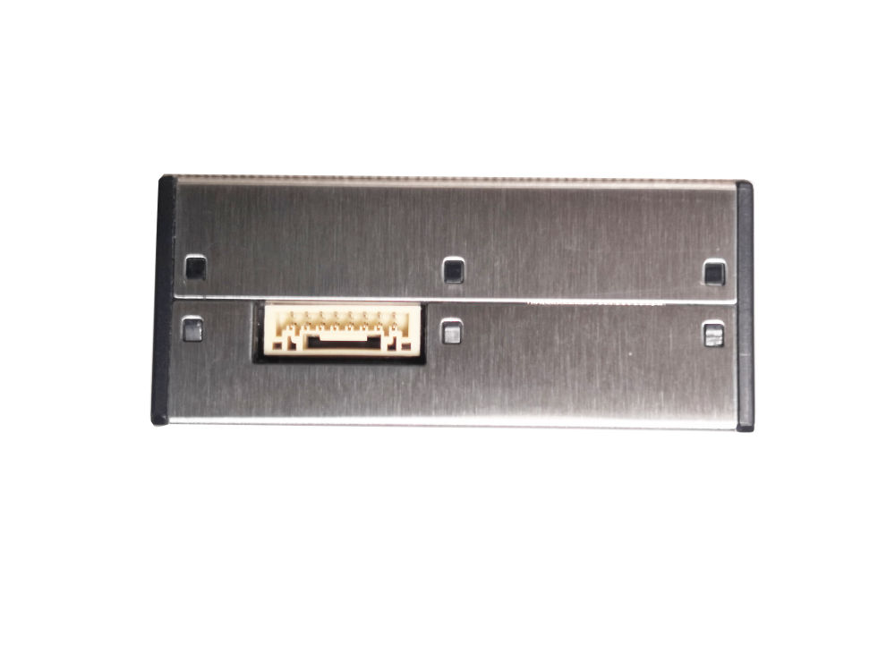
Pin Configuration and Descriptions

The APC1 sensor has a 6-pin interface for power, communication, and control. The pinout is as follows:

Pin Name Description
1 VCC Power supply input (3.3V to 5.0V)
2 GND Ground connection
3 SDA I²C data line
4 SCL I²C clock line
5 INT Interrupt pin for event signaling (optional)
6 NC Not connected (leave unconnected)

Usage Instructions

How to Use the APC1 in a Circuit

  1. Power Supply: Connect the VCC pin to a 3.3V or 5.0V power source and the GND pin to ground.
  2. I²C Communication: Connect the SDA and SCL pins to the corresponding I²C pins on your microcontroller or development board (e.g., Arduino UNO).
  3. Interrupt Pin (Optional): If you want to use the interrupt feature, connect the INT pin to a GPIO pin on your microcontroller. Otherwise, leave it unconnected.
  4. Pull-Up Resistors: Ensure that the I²C lines (SDA and SCL) have appropriate pull-up resistors (typically 4.7kΩ).

Important Considerations and Best Practices

  • Power Stability: Use a stable power supply to avoid measurement inaccuracies.
  • Placement: Place the sensor in an area with good airflow for accurate readings.
  • I²C Address: The default I²C address of the APC1 is 0x5A. Ensure no other devices on the I²C bus share this address.
  • Startup Time: Allow the sensor to stabilize for 30 seconds after power-up before taking measurements.

Example Code for Arduino UNO

Below is an example of how to interface the APC1 with an Arduino UNO using the I²C protocol:

#include <Wire.h>

// Define the I²C address of the APC1 sensor
#define APC1_I2C_ADDRESS 0x5A

void setup() {
  Wire.begin(); // Initialize I²C communication
  Serial.begin(9600); // Initialize serial communication for debugging

  // Wait for the sensor to stabilize
  delay(30000); // 30 seconds stabilization time
  Serial.println("APC1 Sensor Initialized");
}

void loop() {
  Wire.beginTransmission(APC1_I2C_ADDRESS); // Start communication with APC1
  Wire.write(0x00); // Command to request data (example command)
  Wire.endTransmission();

  Wire.requestFrom(APC1_I2C_ADDRESS, 6); // Request 6 bytes of data
  if (Wire.available() == 6) {
    uint16_t pm1 = Wire.read() << 8 | Wire.read(); // PM1.0 concentration
    uint16_t pm25 = Wire.read() << 8 | Wire.read(); // PM2.5 concentration
    uint16_t pm10 = Wire.read() << 8 | Wire.read(); // PM10 concentration

    // Print the air quality data
    Serial.print("PM1.0: ");
    Serial.print(pm1);
    Serial.print(" µg/m³, PM2.5: ");
    Serial.print(pm25);
    Serial.print(" µg/m³, PM10: ");
    Serial.print(pm10);
    Serial.println(" µg/m³");
  } else {
    Serial.println("Error: No data received from APC1");
  }

  delay(1000); // Wait 1 second before the next reading
}

Troubleshooting and FAQs

Common Issues and Solutions

  1. No Data Received from the Sensor

    • Cause: Incorrect I²C wiring or address mismatch.
    • Solution: Verify the SDA and SCL connections and ensure the I²C address matches 0x5A.
  2. Inaccurate Readings

    • Cause: Sensor not stabilized or poor placement.
    • Solution: Allow the sensor to stabilize for 30 seconds after power-up and ensure proper airflow around the sensor.
  3. I²C Communication Errors

    • Cause: Missing pull-up resistors on the I²C lines.
    • Solution: Add 4.7kΩ pull-up resistors to the SDA and SCL lines.
  4. Interrupt Pin Not Working

    • Cause: Interrupt pin not configured in the microcontroller.
    • Solution: Check the microcontroller's GPIO configuration and ensure the INT pin is connected.

FAQs

  1. Can the APC1 operate at 5V?

    • Yes, the APC1 supports a supply voltage range of 3.3V to 5.0V.
  2. What pollutants can the APC1 measure?

    • The APC1 measures particulate matter concentrations for PM1.0, PM2.5, and PM10.
  3. Is the APC1 suitable for outdoor use?

    • The APC1 is designed for indoor use. For outdoor applications, ensure it is protected from extreme conditions and direct exposure to water.
  4. How often should I calibrate the sensor?

    • The APC1 is factory-calibrated and does not require regular calibration. However, periodic validation against a reference device is recommended for critical applications.