How to Use motor: Examples, Pinouts, and Specs
Introduction
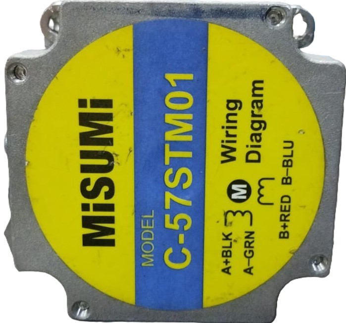
The C-57STM01 motor, manufactured by Misumi, is an electromechanical device designed to convert electrical energy into mechanical energy. This motor is commonly used in applications requiring precise motion control, such as robotics, conveyor systems, and industrial automation. Its robust design and reliable performance make it suitable for both hobbyist projects and professional use.
Explore Projects Built with motor

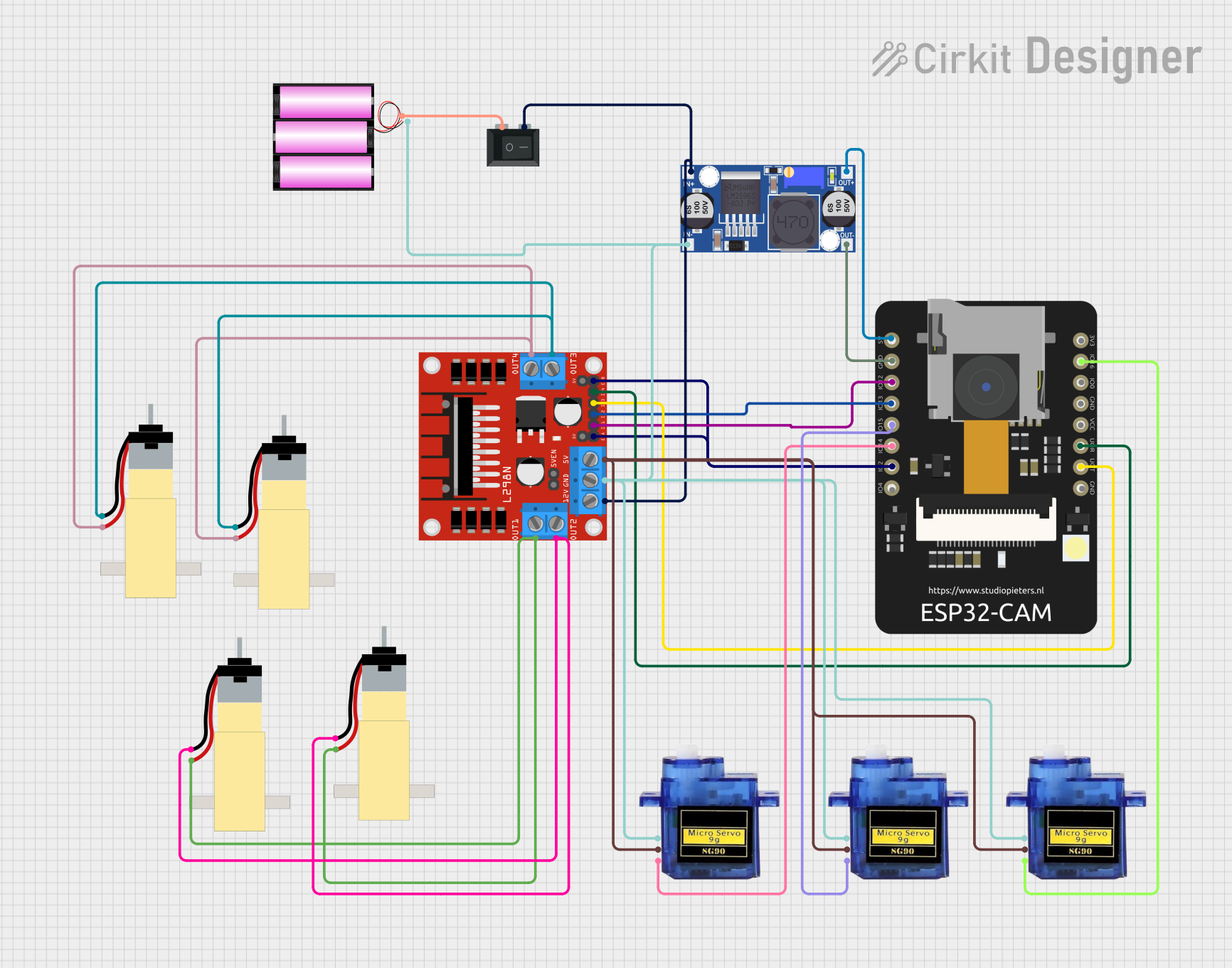
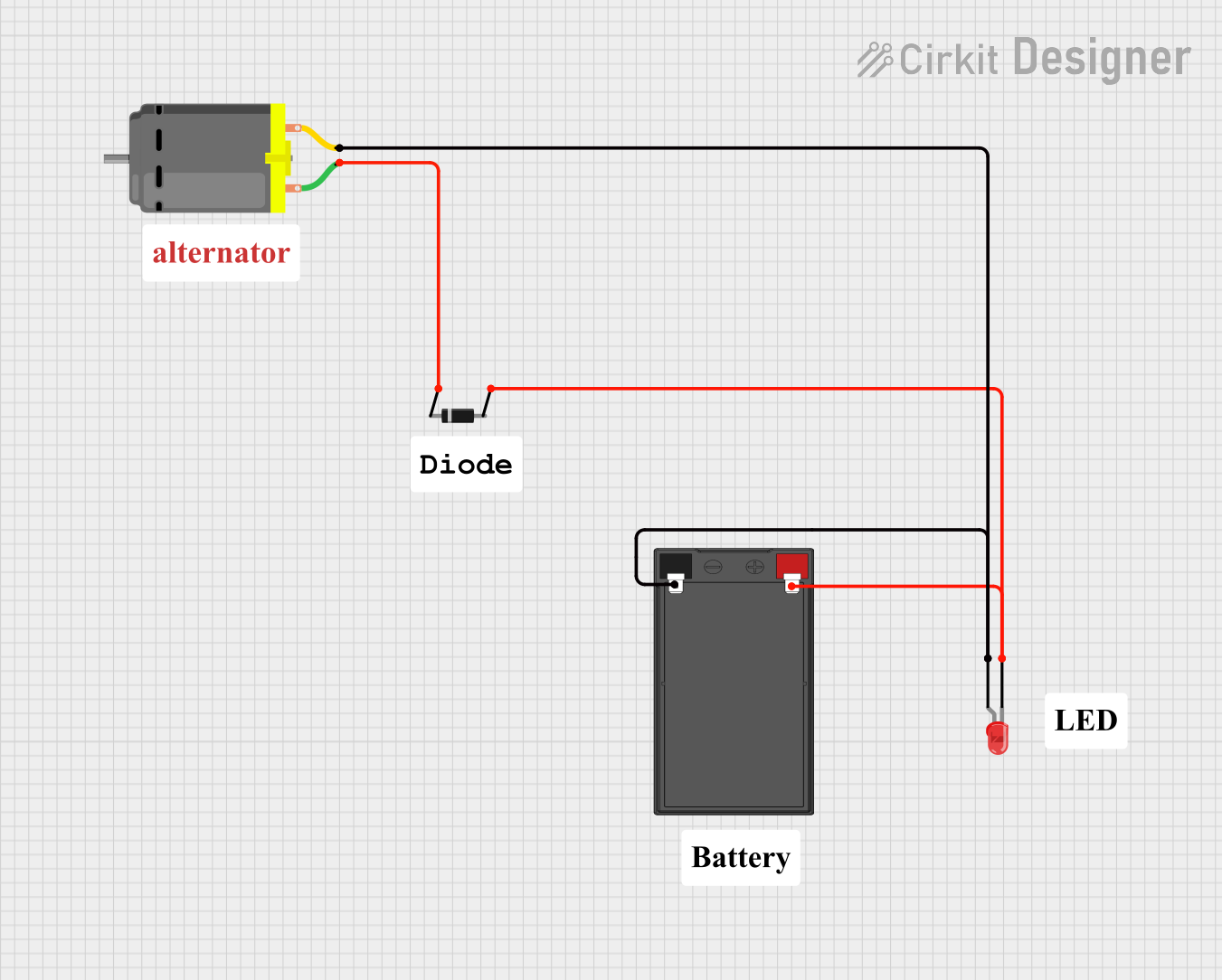
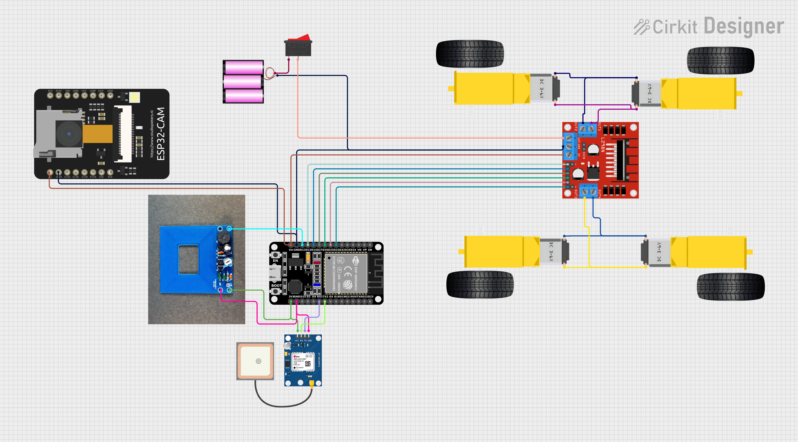
Explore Projects Built with motor
Common Applications
- Robotics and automation systems
- Conveyor belts and material handling
- CNC machines and 3D printers
- Electric vehicles and drones
- HVAC systems and pumps
Technical Specifications
Key Specifications
| Parameter | Value |
|---|---|
| Manufacturer | Misumi |
| Part ID | C-57STM01 |
| Motor Type | Stepper Motor |
| Rated Voltage | 12V DC |
| Rated Current | 1.5A per phase |
| Step Angle | 1.8° |
| Holding Torque | 0.5 Nm |
| Number of Phases | 2 |
| Shaft Diameter | 5 mm |
| Dimensions (L x W x H) | 57 mm x 57 mm x 48 mm |
| Weight | 400 g |
Pin Configuration and Descriptions
The C-57STM01 motor has four wires for its bipolar stepper configuration. The table below describes the pinout:
| Wire Color | Function | Description |
|---|---|---|
| Red | Coil A+ | Positive terminal of Coil A |
| Blue | Coil A- | Negative terminal of Coil A |
| Green | Coil B+ | Positive terminal of Coil B |
| Black | Coil B- | Negative terminal of Coil B |
Usage Instructions
How to Use the Motor in a Circuit
- Power Supply: Ensure the motor is powered by a 12V DC power source capable of supplying at least 1.5A per phase.
- Driver Circuit: Use a stepper motor driver (e.g., A4988 or DRV8825) to control the motor. The driver will handle the current regulation and step sequencing.
- Connections:
- Connect the motor wires to the driver as per the pin configuration.
- Connect the driver's power input to the 12V DC power supply.
- Interface the driver's control pins (e.g., STEP, DIR) with a microcontroller like an Arduino UNO.
- Microcontroller Programming: Write a program to send step and direction signals to the driver to control the motor's movement.
Important Considerations
- Current Limiting: Set the current limit on the driver to 1.5A to prevent overheating or damage to the motor.
- Heat Dissipation: Ensure proper ventilation or use a heatsink if the motor operates continuously under load.
- Step Resolution: Configure the driver for full-step, half-step, or microstepping as needed for your application.
- Wiring: Double-check the wiring to avoid short circuits or incorrect connections.
Example Code for Arduino UNO
Below is an example code snippet to control the C-57STM01 motor using an A4988 driver:
// Define control pins for the A4988 driver
#define STEP_PIN 3  // Pin connected to STEP input on the driver
#define DIR_PIN 4   // Pin connected to DIR input on the driver

void setup() {
  pinMode(STEP_PIN, OUTPUT); // Set STEP pin as output
  pinMode(DIR_PIN, OUTPUT);  // Set DIR pin as output

  digitalWrite(DIR_PIN, HIGH); // Set direction (HIGH = clockwise, LOW = counterclockwise)
}

void loop() {
  // Generate step pulses to move the motor
  digitalWrite(STEP_PIN, HIGH); // Set STEP pin HIGH
  delayMicroseconds(1000);      // Wait 1 millisecond
  digitalWrite(STEP_PIN, LOW);  // Set STEP pin LOW
  delayMicroseconds(1000);      // Wait 1 millisecond
}
Note: Adjust the delay values to control the motor's speed. A shorter delay results in faster rotation.
Troubleshooting and FAQs
Common Issues and Solutions
Motor Not Moving:
- Cause: Incorrect wiring or loose connections.
- Solution: Verify the wiring matches the pin configuration table and ensure all connections are secure.
Motor Vibrates but Doesn't Rotate:
- Cause: Incorrect step sequence or insufficient current.
- Solution: Check the stepper driver settings and ensure the current limit is set to 1.5A.
Overheating:
- Cause: Excessive current or prolonged operation under load.
- Solution: Reduce the current limit on the driver or add a cooling mechanism.
Skipping Steps:
- Cause: Load exceeds the motor's holding torque.
- Solution: Reduce the load or use a motor with higher torque.
FAQs
Q: Can I power the motor with a voltage higher than 12V?
- A: No, exceeding the rated voltage may damage the motor. Use a 12V DC power supply.
Q: What is the maximum speed of the motor?
- A: The maximum speed depends on the step rate and load. Typically, it can achieve up to 1000 RPM under light loads.
Q: Can I use this motor with a unipolar driver?
- A: No, the C-57STM01 is a bipolar stepper motor and requires a bipolar driver.
Q: How do I reverse the motor's direction?
- A: Toggle the DIR pin on the driver (HIGH for clockwise, LOW for counterclockwise).
By following this documentation, users can effectively integrate the C-57STM01 motor into their projects and troubleshoot common issues with ease.