How to Use DC Power Monitor with Wifi: Examples, Pinouts, and Specs
Introduction
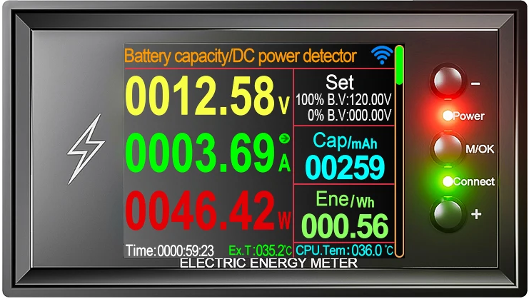
The DC Power Monitor with WiFi by 테무 (Part ID: DC Power Monitor with Wifi) is a versatile device designed to measure and display the direct current (DC) power usage of a circuit. Equipped with Wi-Fi connectivity, it allows for remote monitoring and data logging, making it an ideal solution for applications requiring real-time power analysis and control.
Explore Projects Built with DC Power Monitor with Wifi

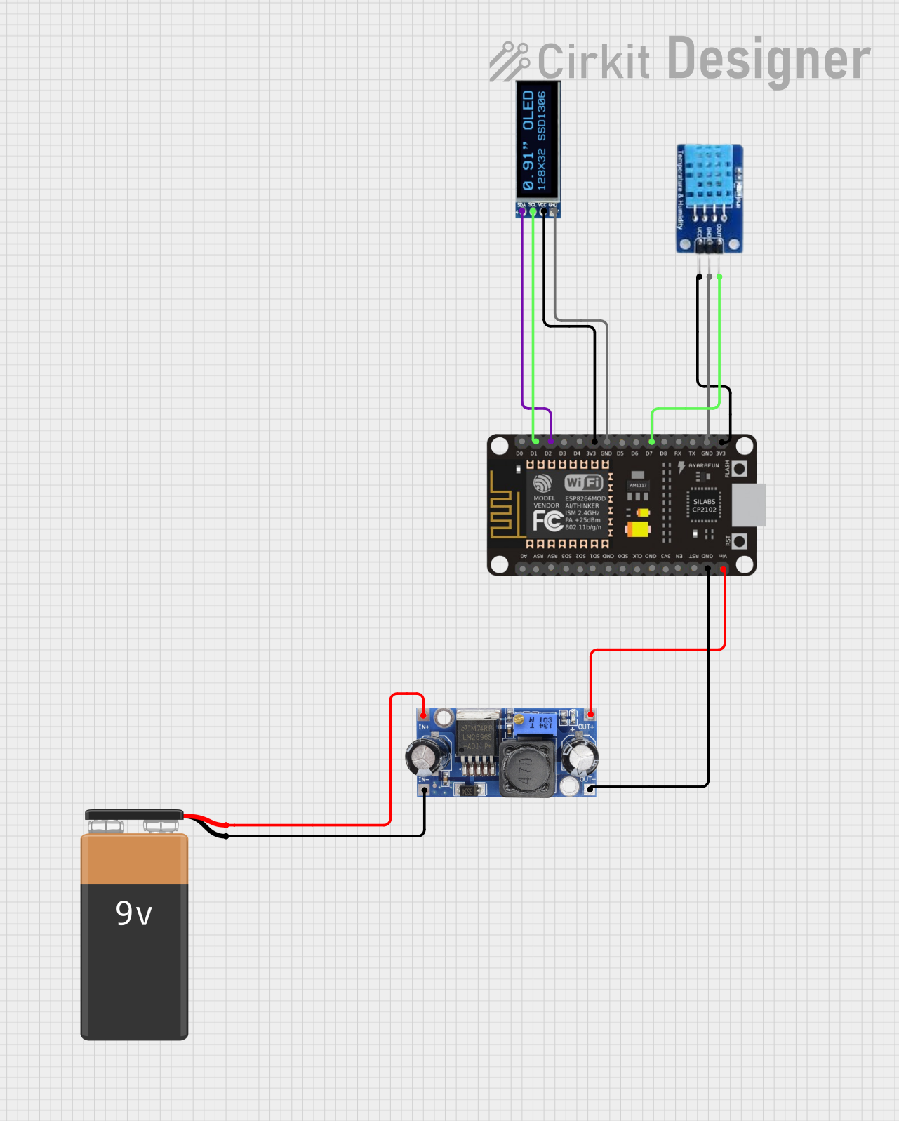
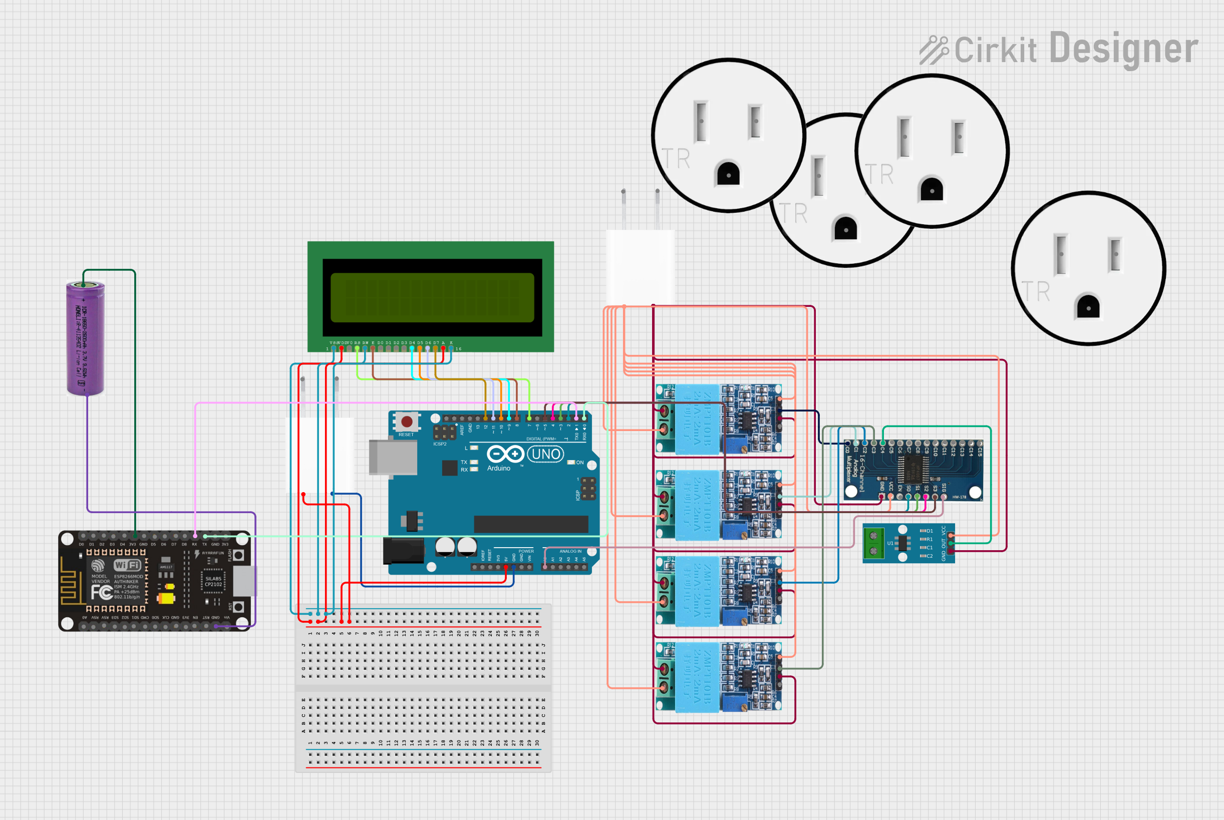
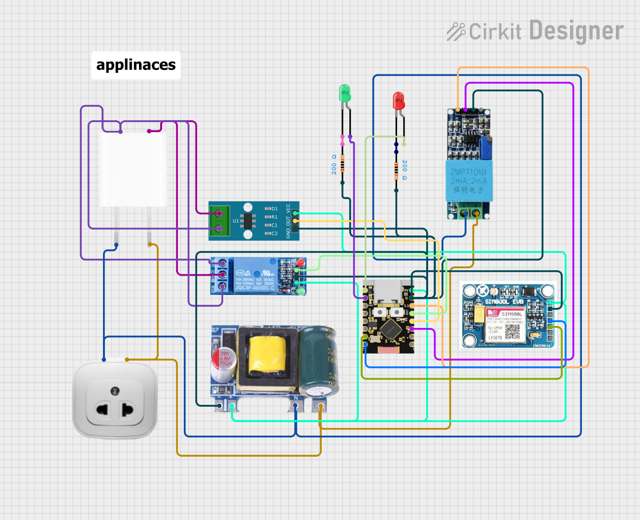
Explore Projects Built with DC Power Monitor with Wifi
Common Applications and Use Cases
- Monitoring power consumption in renewable energy systems (e.g., solar panels, batteries)
- IoT-based energy management systems
- Remote power usage tracking for industrial and home automation
- Data logging for research and development projects
- Overcurrent and power anomaly detection in DC circuits
Technical Specifications
Below are the key technical details of the DC Power Monitor with WiFi:
| Parameter | Value |
|---|---|
| Input Voltage Range | 0–60 V DC |
| Current Measurement Range | 0–30 A DC |
| Power Measurement Range | 0–1800 W |
| Accuracy | ±1% |
| Wi-Fi Standard | IEEE 802.11 b/g/n (2.4 GHz) |
| Communication Protocol | HTTP, MQTT |
| Display Type | OLED (128x64 resolution) |
| Operating Temperature | -10°C to 60°C |
| Power Supply | 5 V DC (via micro-USB or terminal) |
| Dimensions | 80 mm x 50 mm x 25 mm |
Pin Configuration and Descriptions
The device features the following input/output terminals and connectors:
| Pin/Connector | Description |
|---|---|
| VIN+ | Positive DC voltage input for power measurement |
| VIN- | Negative DC voltage input for power measurement |
| I+ | Positive current input for current sensing |
| I- | Negative current input for current sensing |
| GND | Ground connection for the device |
| 5V | 5 V DC power input (via micro-USB or terminal block) |
| TX | UART transmit pin for serial communication |
| RX | UART receive pin for serial communication |
Usage Instructions
How to Use the Component in a Circuit
Powering the Device:
Connect a 5 V DC power source to the5VandGNDterminals or use the micro-USB port.Connecting the Circuit for Measurement:
- Connect the positive DC voltage line of the circuit to
VIN+and the negative line toVIN-. - For current measurement, connect the
I+andI-terminals in series with the load.
- Connect the positive DC voltage line of the circuit to
Wi-Fi Configuration:
- Power on the device and connect to its default Wi-Fi hotspot (SSID:
DCMonitor_XXXX). - Open a web browser and navigate to
192.168.4.1to access the configuration page. - Enter your Wi-Fi credentials and save the settings. The device will reboot and connect to your network.
- Power on the device and connect to its default Wi-Fi hotspot (SSID:
Data Access:
- Use the provided IP address to access the web interface for real-time monitoring.
- For MQTT integration, configure the broker details via the web interface.
Important Considerations and Best Practices
- Ensure the input voltage and current do not exceed the specified ranges to avoid damage.
- Use appropriately rated wires and connectors for high-current applications.
- Place the device in a well-ventilated area to prevent overheating.
- Secure the Wi-Fi connection with a strong password to prevent unauthorized access.
- For accurate measurements, calibrate the device periodically using the web interface.
Arduino UNO Integration Example
The DC Power Monitor can communicate with an Arduino UNO via UART. Below is an example code snippet to read data from the device:
#include <SoftwareSerial.h>

// Define RX and TX pins for SoftwareSerial
SoftwareSerial dcMonitor(10, 11); // RX = pin 10, TX = pin 11

void setup() {
  Serial.begin(9600); // Initialize Serial Monitor
  dcMonitor.begin(9600); // Initialize communication with DC Power Monitor

  Serial.println("DC Power Monitor with WiFi - Arduino Integration");
}

void loop() {
  if (dcMonitor.available()) {
    // Read data from the DC Power Monitor
    String data = dcMonitor.readStringUntil('\n');

    // Print the received data to the Serial Monitor
    Serial.println("Received Data: " + data);
  }

  delay(1000); // Wait for 1 second before the next read
}
Troubleshooting and FAQs
Common Issues and Solutions
Device Not Powering On:
- Ensure the power supply is providing 5 V DC.
- Check the connections to the
5VandGNDterminals or the micro-USB cable.
Wi-Fi Connection Fails:
- Verify that the entered Wi-Fi credentials are correct.
- Ensure the router operates on the 2.4 GHz band (not 5 GHz).
- Reset the device by holding the reset button for 5 seconds and reconfigure.
Inaccurate Measurements:
- Check that the input voltage and current are within the specified ranges.
- Perform a calibration via the web interface.
No Data on Arduino:
- Verify the RX and TX connections between the Arduino and the device.
- Ensure the baud rate in the Arduino code matches the device's UART settings.
FAQs
Q1: Can the device log data without an active Wi-Fi connection?
A1: No, the device requires Wi-Fi for remote data logging. However, real-time data can still be viewed on the OLED display.
Q2: Is the device compatible with 24 V battery systems?
A2: Yes, the device supports up to 60 V DC, making it suitable for 24 V systems.
Q3: How do I update the firmware?
A3: Firmware updates can be performed via the web interface. Navigate to the "Firmware Update" section and upload the provided firmware file.
Q4: Can I use the device with a 5 GHz Wi-Fi network?
A4: No, the device only supports 2.4 GHz Wi-Fi networks.
Q5: What happens if the measured current exceeds 30 A?
A5: The device may become damaged. Always ensure the current remains within the specified range. Use external current shunts if necessary.
This concludes the documentation for the DC Power Monitor with WiFi by 테무. For further assistance, refer to the manufacturer's support resources.