Cirkit Designer Logo
Cirkit Designer
Your all-in-one circuit design IDE
Home / 
Component Documentation

How to Use VRX1.2: Examples, Pinouts, and Specs

Image of VRX1.2
Cirkit Designer LogoDesign with VRX1.2 in Cirkit Designer

Introduction

The VRX1.2 is a high-performance voltage regulator designed to maintain a constant and stable output voltage, even in the presence of fluctuations in input voltage or varying load conditions. This component is essential for ensuring reliable power delivery to sensitive electronic circuits, protecting them from damage caused by voltage instability.

Explore Projects Built with VRX1.2

Use Cirkit Designer to design, explore, and prototype these projects online. Some projects support real-time simulation. Click "Open Project" to start designing instantly!
Satellite-Based Timing and Navigation System with SDR and Atomic Clock Synchronization
Image of GPS 시스템 측정 구성도_Confirm: A project utilizing VRX1.2 in a practical application
This circuit appears to be a complex system involving power supply management, GPS and timing synchronization, and data communication. It includes a SI-TEX G1 Satellite Compass for GPS data, an XHTF1021 Atomic Rubidium Clock for precise timing, and Ettus USRP B200 units for software-defined radio communication. Power is supplied through various SMPS units and distributed via terminal blocks and DC jacks. Data communication is facilitated by Beelink MINI S12 N95 computers, RS232 splitters, and a 1000BASE-T Media Converter for network connectivity. RF Directional Couplers are used to interface antennas with the USRP units, and the entire system is likely contained within cases for protection and organization.
Cirkit Designer LogoOpen Project in Cirkit Designer
Battery-Powered Line Following Robot with IR Sensors and Cytron URC10 Motor Controller
Image of URC10 SUMO AUTO: A project utilizing VRX1.2 in a practical application
This circuit is a robotic control system that uses multiple IR sensors for line detection and obstacle avoidance, powered by a 3S LiPo battery. The Cytron URC10 motor driver, controlled by a microcontroller, drives two GM25 DC motors based on input from the sensors and a rocker switch, with a 7-segment panel voltmeter displaying the battery voltage.
Cirkit Designer LogoOpen Project in Cirkit Designer
Arduino Pro Mini and ACS712 Current Sensor-Based Jeti EX Telemetry System
Image of CUR30J: A project utilizing VRX1.2 in a practical application
This circuit integrates an Arduino Pro Mini with a Jeti Rex Receiver and an ACS712 current sensor to measure and transmit current, voltage, power, capacity, and rotation data. The Arduino processes sensor data and communicates it to the Jeti Rex Receiver for telemetry purposes.
Cirkit Designer LogoOpen Project in Cirkit Designer
Arduino and ESP8266 Wi-Fi Controlled Vibration Detection System with OLED Display and Relay Output
Image of Earthquake Security System: A project utilizing VRX1.2 in a practical application
This circuit features an Arduino UNO that processes inputs from vibration and accelerometer sensors, controls relays for external device actuation, and communicates over WiFi. It includes a step-down converter for power management and an OLED display for data output. A red light indicator is used for visual status alerts.
Cirkit Designer LogoOpen Project in Cirkit Designer

Explore Projects Built with VRX1.2

Use Cirkit Designer to design, explore, and prototype these projects online. Some projects support real-time simulation. Click "Open Project" to start designing instantly!
Image of GPS 시스템 측정 구성도_Confirm: A project utilizing VRX1.2 in a practical application
Satellite-Based Timing and Navigation System with SDR and Atomic Clock Synchronization
This circuit appears to be a complex system involving power supply management, GPS and timing synchronization, and data communication. It includes a SI-TEX G1 Satellite Compass for GPS data, an XHTF1021 Atomic Rubidium Clock for precise timing, and Ettus USRP B200 units for software-defined radio communication. Power is supplied through various SMPS units and distributed via terminal blocks and DC jacks. Data communication is facilitated by Beelink MINI S12 N95 computers, RS232 splitters, and a 1000BASE-T Media Converter for network connectivity. RF Directional Couplers are used to interface antennas with the USRP units, and the entire system is likely contained within cases for protection and organization.
Cirkit Designer LogoOpen Project in Cirkit Designer
Image of URC10 SUMO AUTO: A project utilizing VRX1.2 in a practical application
Battery-Powered Line Following Robot with IR Sensors and Cytron URC10 Motor Controller
This circuit is a robotic control system that uses multiple IR sensors for line detection and obstacle avoidance, powered by a 3S LiPo battery. The Cytron URC10 motor driver, controlled by a microcontroller, drives two GM25 DC motors based on input from the sensors and a rocker switch, with a 7-segment panel voltmeter displaying the battery voltage.
Cirkit Designer LogoOpen Project in Cirkit Designer
Image of CUR30J: A project utilizing VRX1.2 in a practical application
Arduino Pro Mini and ACS712 Current Sensor-Based Jeti EX Telemetry System
This circuit integrates an Arduino Pro Mini with a Jeti Rex Receiver and an ACS712 current sensor to measure and transmit current, voltage, power, capacity, and rotation data. The Arduino processes sensor data and communicates it to the Jeti Rex Receiver for telemetry purposes.
Cirkit Designer LogoOpen Project in Cirkit Designer
Image of Earthquake Security System: A project utilizing VRX1.2 in a practical application
Arduino and ESP8266 Wi-Fi Controlled Vibration Detection System with OLED Display and Relay Output
This circuit features an Arduino UNO that processes inputs from vibration and accelerometer sensors, controls relays for external device actuation, and communicates over WiFi. It includes a step-down converter for power management and an OLED display for data output. A red light indicator is used for visual status alerts.
Cirkit Designer LogoOpen Project in Cirkit Designer

Common Applications and Use Cases

  • Power supply stabilization for microcontrollers, sensors, and other electronic components.
  • Voltage regulation in battery-powered devices.
  • Use in embedded systems, robotics, and IoT devices.
  • Protection of sensitive circuits from voltage spikes or drops.

Technical Specifications

The VRX1.2 is designed to deliver consistent performance under a wide range of operating conditions. Below are its key technical specifications:

Parameter Value
Input Voltage Range 4.5V to 20V
Output Voltage 3.3V or 5V (fixed versions)
Maximum Output Current 1.2A
Dropout Voltage 0.5V (typical at 1A load)
Quiescent Current 5mA (typical)
Operating Temperature -40°C to +85°C
Package Type TO-220, SOT-223, or SMD

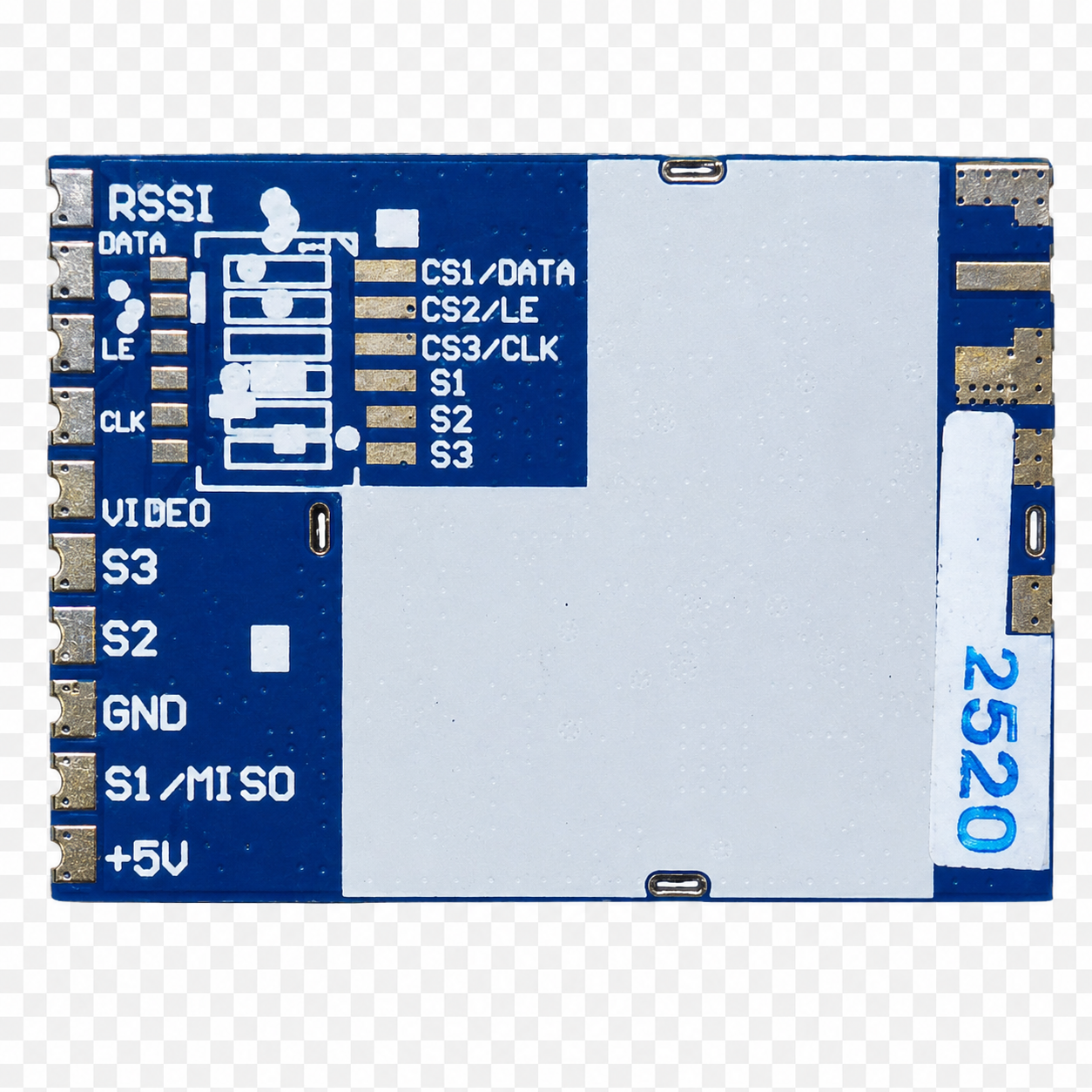
Pin Configuration and Descriptions

The VRX1.2 typically comes in a 3-pin configuration. Below is the pinout description:

Pin Number Pin Name Description
1 Input (VIN) Connect to the unregulated input voltage source.
2 Ground (GND) Common ground for input and output.
3 Output (VOUT) Regulated output voltage.

Usage Instructions

How to Use the VRX1.2 in a Circuit

  1. Input Voltage Connection: Connect the unregulated input voltage to the VIN pin. Ensure the input voltage is within the specified range (4.5V to 20V).
  2. Output Voltage Connection: Connect the load to the VOUT pin. The output voltage will be regulated to 3.3V or 5V, depending on the VRX1.2 version.
  3. Ground Connection: Connect the GND pin to the common ground of the circuit.
  4. Capacitor Placement: Place a capacitor (e.g., 10µF) between VIN and GND to filter input noise. Similarly, place a capacitor (e.g., 10µF or 22µF) between VOUT and GND to stabilize the output voltage.

Important Considerations and Best Practices

  • Heat Dissipation: If the VRX1.2 is operating at high currents, use a heatsink or ensure proper ventilation to prevent overheating.
  • Input Voltage Margin: Ensure the input voltage is at least 1V higher than the output voltage to account for the dropout voltage.
  • Capacitor Selection: Use low-ESR capacitors for better performance and stability.
  • Reverse Polarity Protection: Add a diode in series with the input to protect the regulator from reverse polarity damage.

Example: Using VRX1.2 with an Arduino UNO

The VRX1.2 can be used to power an Arduino UNO by providing a stable 5V supply. Below is an example circuit and code:

Circuit Setup

  1. Connect a 9V battery to the VIN pin of the VRX1.2.
  2. Connect the VOUT pin to the 5V pin of the Arduino UNO.
  3. Connect the GND pin of the VRX1.2 to the GND pin of the Arduino UNO.

Example Code

// Example code for Arduino UNO powered by VRX1.2 voltage regulator
// This code blinks an LED connected to pin 13.

void setup() {
  pinMode(13, OUTPUT); // Set pin 13 as an output pin
}

void loop() {
  digitalWrite(13, HIGH); // Turn the LED on
  delay(1000);            // Wait for 1 second
  digitalWrite(13, LOW);  // Turn the LED off
  delay(1000);            // Wait for 1 second
}

Troubleshooting and FAQs

Common Issues and Solutions

  1. No Output Voltage:

    • Cause: Input voltage is below the minimum required value.
    • Solution: Ensure the input voltage is within the specified range (4.5V to 20V).
  2. Overheating:

    • Cause: Excessive current draw or insufficient heat dissipation.
    • Solution: Use a heatsink or reduce the load current.
  3. Output Voltage Instability:

    • Cause: Missing or improperly placed capacitors.
    • Solution: Add low-ESR capacitors as recommended in the usage instructions.
  4. Reverse Polarity Damage:

    • Cause: Input voltage connected with reversed polarity.
    • Solution: Add a diode in series with the input to prevent damage.

FAQs

  • Q: Can the VRX1.2 provide adjustable output voltage?
    A: No, the VRX1.2 is available in fixed output voltage versions (3.3V or 5V).

  • Q: What is the maximum current the VRX1.2 can supply?
    A: The VRX1.2 can supply up to 1.2A of current.

  • Q: Can I use the VRX1.2 with a 12V input to power a 5V circuit?
    A: Yes, as long as the input voltage is within the specified range and the load does not exceed 1.2A.

  • Q: Do I need to use heatsinks with the VRX1.2?
    A: Heatsinks are recommended if the regulator operates at high currents or if there is significant voltage drop between input and output.