Cirkit Designer Logo
Cirkit Designer
Your all-in-one circuit design IDE
Home / 
Component Documentation

How to Use nodemcu esp8266: Examples, Pinouts, and Specs

Image of nodemcu esp8266
Cirkit Designer LogoDesign with nodemcu esp8266 in Cirkit Designer

Introduction

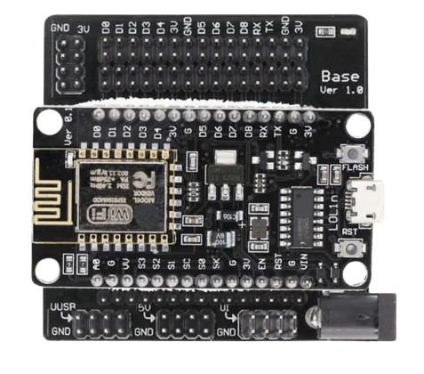
The NodeMCU ESP8266 is an open-source IoT platform based on the ESP8266 Wi-Fi module. It features a built-in Lua interpreter and supports the Arduino IDE, making it an excellent choice for developing connected devices. With its integrated Wi-Fi capabilities, GPIO pins, and ease of programming, the NodeMCU ESP8266 is widely used in IoT applications, home automation, and wireless sensor networks.

Explore Projects Built with nodemcu esp8266

Use Cirkit Designer to design, explore, and prototype these projects online. Some projects support real-time simulation. Click "Open Project" to start designing instantly!
Wi-Fi Controlled Smart Home Automation with ESP8266 and Relay Module
Image of Vox Domus: A project utilizing nodemcu esp8266 in a practical application
This circuit is a smart home automation system using an ESP8266 NodeMCU to control a 2-channel relay module, which in turn controls a fan and a bulb. The system is powered by a 5V adapter and a 9V battery, and it uses WiFi to connect to the SinricPro platform for remote control via a mobile app.
Cirkit Designer LogoOpen Project in Cirkit Designer
ESP8266 NodeMCU Controlled GPS Tracker with Relay-Activated Gearmotor
Image of Geo Fence: A project utilizing nodemcu esp8266 in a practical application
This circuit features a GPS NEO 6M module interfaced with two ESP8266 NodeMCU microcontrollers for GPS data acquisition. One NodeMCU is connected to the GPS module's TX and RX pins for communication, and both NodeMCUs are powered by a shared 3.3V supply. Additionally, a relay module controlled by the second NodeMCU switches a hobby gearmotor on and off, with the motor's power supplied by a 9V battery.
Cirkit Designer LogoOpen Project in Cirkit Designer
ESP8266 NodeMCU-Based Smart Irrigation System with GSM Reporting and Environmental Monitoring
Image of Ismail_Fab Project: A project utilizing nodemcu esp8266 in a practical application
This circuit features an ESP8266 NodeMCU microcontroller connected to various sensors and modules for environmental monitoring and control. It interfaces with a DHT11 temperature and humidity sensor, a soil moisture sensor, and a GSM SIM900 module for communication. Additionally, the circuit can control a 12V fan and a 5V mini water pump via a relay, and it includes a step-up voltage regulator to supply the necessary voltages, as well as an LCD display for user interface.
Cirkit Designer LogoOpen Project in Cirkit Designer
ESP8266 NodeMCU Controlled NRF24L01 Wireless Communication Module
Image of WSN 2: A project utilizing nodemcu esp8266 in a practical application
This circuit connects an NRF24L01 wireless transceiver module to an ESP8266 NodeMCU microcontroller. The ESP8266 controls the NRF24L01 via SPI communication, using its GPIO pins D1, D2, D5, D6, and D7 for CE, CSN, SCK, MISO, and MOSI respectively. The circuit is designed for wireless data communication, with the ESP8266 managing the network protocol and data handling, while the NRF24L01 handles the RF communication.
Cirkit Designer LogoOpen Project in Cirkit Designer

Explore Projects Built with nodemcu esp8266

Use Cirkit Designer to design, explore, and prototype these projects online. Some projects support real-time simulation. Click "Open Project" to start designing instantly!
Image of Vox Domus: A project utilizing nodemcu esp8266 in a practical application
Wi-Fi Controlled Smart Home Automation with ESP8266 and Relay Module
This circuit is a smart home automation system using an ESP8266 NodeMCU to control a 2-channel relay module, which in turn controls a fan and a bulb. The system is powered by a 5V adapter and a 9V battery, and it uses WiFi to connect to the SinricPro platform for remote control via a mobile app.
Cirkit Designer LogoOpen Project in Cirkit Designer
Image of Geo Fence: A project utilizing nodemcu esp8266 in a practical application
ESP8266 NodeMCU Controlled GPS Tracker with Relay-Activated Gearmotor
This circuit features a GPS NEO 6M module interfaced with two ESP8266 NodeMCU microcontrollers for GPS data acquisition. One NodeMCU is connected to the GPS module's TX and RX pins for communication, and both NodeMCUs are powered by a shared 3.3V supply. Additionally, a relay module controlled by the second NodeMCU switches a hobby gearmotor on and off, with the motor's power supplied by a 9V battery.
Cirkit Designer LogoOpen Project in Cirkit Designer
Image of Ismail_Fab Project: A project utilizing nodemcu esp8266 in a practical application
ESP8266 NodeMCU-Based Smart Irrigation System with GSM Reporting and Environmental Monitoring
This circuit features an ESP8266 NodeMCU microcontroller connected to various sensors and modules for environmental monitoring and control. It interfaces with a DHT11 temperature and humidity sensor, a soil moisture sensor, and a GSM SIM900 module for communication. Additionally, the circuit can control a 12V fan and a 5V mini water pump via a relay, and it includes a step-up voltage regulator to supply the necessary voltages, as well as an LCD display for user interface.
Cirkit Designer LogoOpen Project in Cirkit Designer
Image of WSN 2: A project utilizing nodemcu esp8266 in a practical application
ESP8266 NodeMCU Controlled NRF24L01 Wireless Communication Module
This circuit connects an NRF24L01 wireless transceiver module to an ESP8266 NodeMCU microcontroller. The ESP8266 controls the NRF24L01 via SPI communication, using its GPIO pins D1, D2, D5, D6, and D7 for CE, CSN, SCK, MISO, and MOSI respectively. The circuit is designed for wireless data communication, with the ESP8266 managing the network protocol and data handling, while the NRF24L01 handles the RF communication.
Cirkit Designer LogoOpen Project in Cirkit Designer

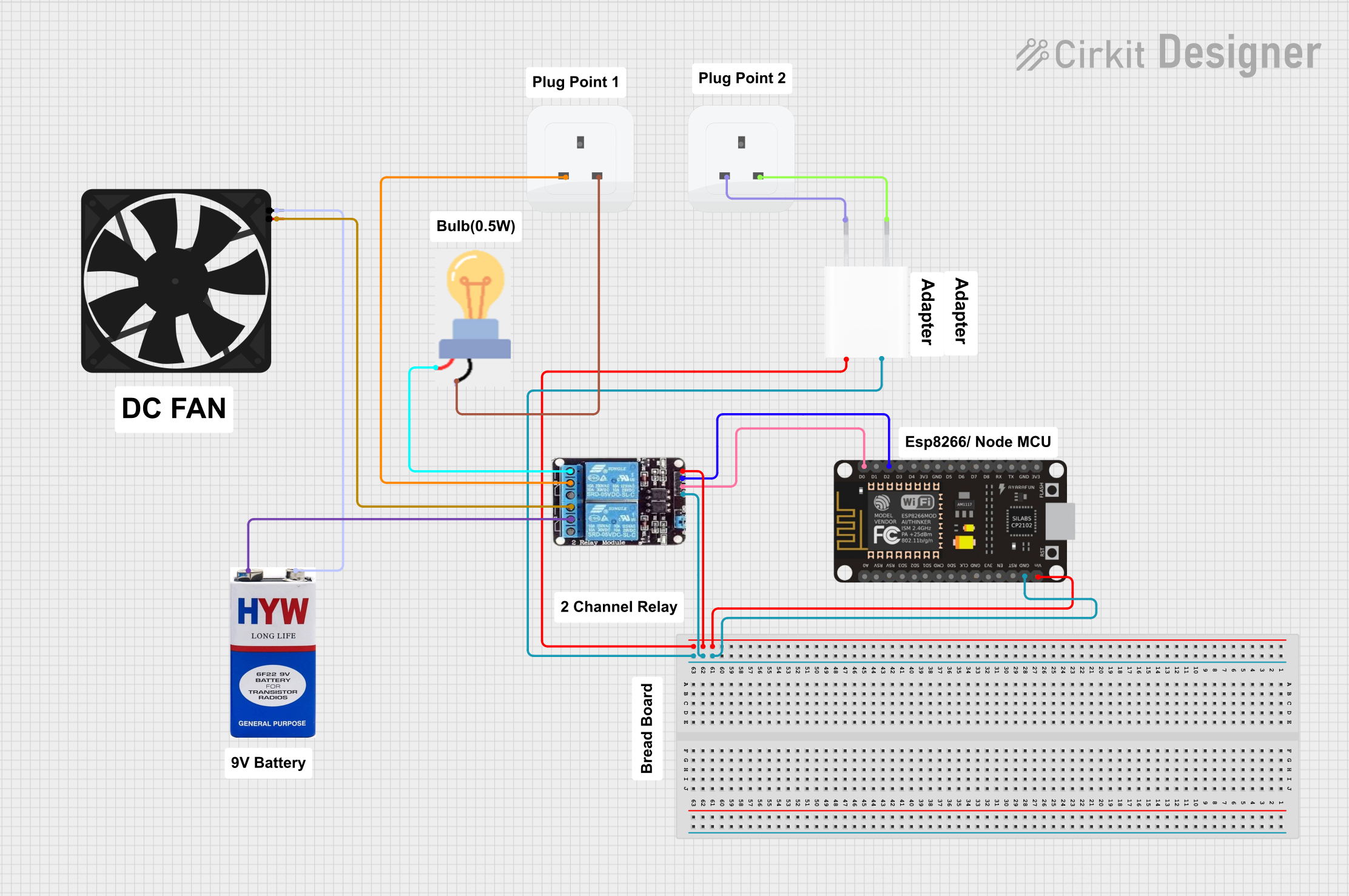
Common Applications and Use Cases

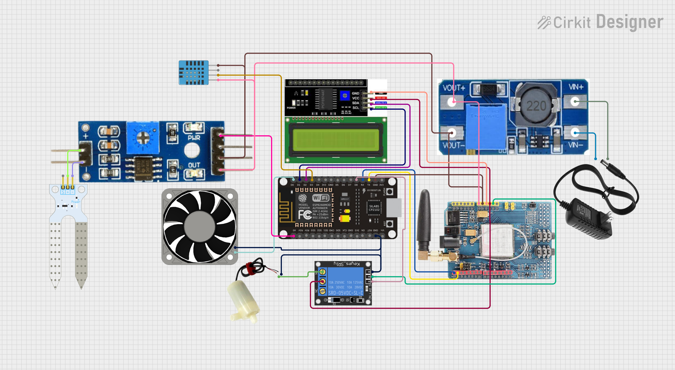
  • Home automation systems (e.g., smart lights, thermostats)
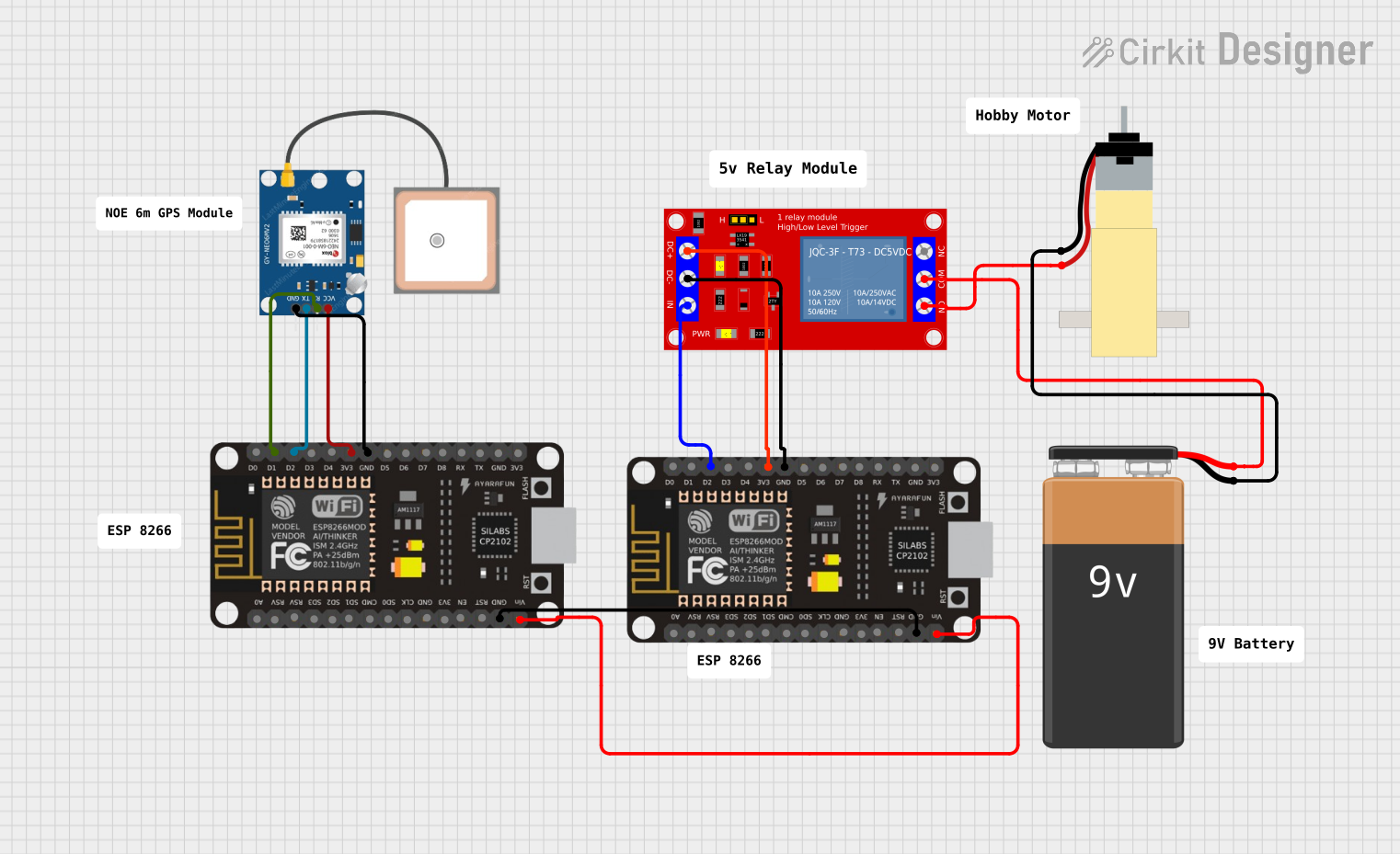
  • Wireless sensor networks
  • IoT prototyping and development
  • Remote monitoring and control
  • Data logging and cloud integration

Technical Specifications

The NodeMCU ESP8266 is equipped with a powerful ESP8266 microcontroller and additional components to simplify development. Below are its key technical details:

Key Technical Details

  • Microcontroller: ESP8266
  • Operating Voltage: 3.3V
  • Input Voltage: 4.5V–10V (via VIN pin) or 5V (via USB)
  • Digital I/O Pins: 11 (D0–D10)
  • Analog Input Pins: 1 (A0, 10-bit resolution)
  • Wi-Fi Standard: 802.11 b/g/n
  • Flash Memory: 4MB (varies by model)
  • Clock Speed: 80MHz (can be overclocked to 160MHz)
  • Power Consumption: ~70mA (idle), ~200mA (transmitting)
  • Communication Protocols: UART, SPI, I2C
  • Dimensions: 49mm x 26mm

Pin Configuration and Descriptions

The NodeMCU ESP8266 has a total of 30 pins. Below is the pinout and description:

Pin Name Type Description
VIN Power Input External power input (4.5V–10V).
3V3 Power Output Provides 3.3V output for external components.
GND Ground Ground connection.
D0–D10 Digital I/O General-purpose digital input/output pins.
A0 Analog Input Analog input pin (0–3.3V, 10-bit resolution).
TX UART TX UART transmit pin for serial communication.
RX UART RX UART receive pin for serial communication.
EN Enable Chip enable pin. Pull high to enable the module.
RST Reset Resets the module when pulled low.
GPIO0, GPIO2 Digital I/O General-purpose I/O pins with special boot mode functions.
SD3, SD2 SPI Pins SPI data pins for external peripherals.

Usage Instructions

The NodeMCU ESP8266 is easy to use and can be programmed using the Arduino IDE or Lua scripting. Below are the steps to get started and important considerations:

Getting Started with Arduino IDE

  1. Install the ESP8266 Board Package:

    • Open the Arduino IDE.
    • Go to File > Preferences.
    • In the "Additional Board Manager URLs" field, add:
      http://arduino.esp8266.com/stable/package_esp8266com_index.json
    • Go to Tools > Board > Boards Manager, search for "ESP8266", and install the package.
  2. Connect the NodeMCU to Your Computer:

    • Use a micro-USB cable to connect the NodeMCU to your computer.
    • Select the correct port under Tools > Port.
  3. Select the Board:

    • Go to Tools > Board and select "NodeMCU 1.0 (ESP-12E Module)".
  4. Write and Upload Code:

    • Write your code in the Arduino IDE.
    • Click the upload button to flash the code to the NodeMCU.

Example Code: Blink an LED

The following example demonstrates how to blink an LED connected to GPIO2 (D4):

// Define the pin for the LED
const int ledPin = D4; // GPIO2 corresponds to D4 on the NodeMCU

void setup() {
  pinMode(ledPin, OUTPUT); // Set the LED pin as an output
}

void loop() {
  digitalWrite(ledPin, HIGH); // Turn the LED on
  delay(1000);               // Wait for 1 second
  digitalWrite(ledPin, LOW);  // Turn the LED off
  delay(1000);               // Wait for 1 second
}

Important Considerations

  • Power Supply: Ensure the NodeMCU is powered with a stable 5V supply via USB or VIN. Avoid exceeding the voltage limits.
  • GPIO Voltage Levels: The GPIO pins operate at 3.3V. Connecting 5V signals directly may damage the module.
  • Wi-Fi Configuration: Use the WiFi library in the Arduino IDE to connect to Wi-Fi networks.
  • Boot Modes: Ensure GPIO0 and GPIO2 are correctly configured for normal operation or flashing firmware.

Troubleshooting and FAQs

Common Issues and Solutions

  1. The NodeMCU is not detected by the computer:

    • Ensure the USB cable is functional and supports data transfer.
    • Install the correct USB-to-serial driver (e.g., CH340 or CP2102).
  2. Upload fails with "esptool.FatalError: Failed to connect to ESP8266":

    • Check that the correct port is selected in the Arduino IDE.
    • Ensure the NodeMCU is in flashing mode by holding the FLASH button while pressing RESET.
  3. Wi-Fi connection issues:

    • Verify the SSID and password in your code.
    • Ensure the Wi-Fi network is within range and supports 2.4GHz (ESP8266 does not support 5GHz).
  4. GPIO pins not working as expected:

    • Double-check the pin mapping (e.g., D4 corresponds to GPIO2).
    • Avoid using reserved pins like GPIO0 and GPIO15 for general I/O.

FAQs

  • Can I power the NodeMCU with a battery?
    Yes, you can use a 3.7V LiPo battery or a 5V power source connected to the VIN pin.

  • What is the maximum current the GPIO pins can source/sink?
    Each GPIO pin can source/sink up to 12mA. For higher currents, use an external transistor or relay.

  • Can I use the NodeMCU with sensors and modules?
    Yes, the NodeMCU supports I2C, SPI, and UART protocols, making it compatible with a wide range of sensors and modules.

By following this documentation, you can effectively use the NodeMCU ESP8266 for your IoT projects.