How to Use OVERLLOAD RELAY 37 TO 50 A: Examples, Pinouts, and Specs
Introduction
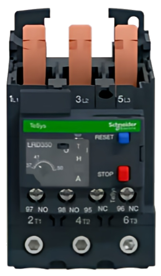
The Schneider LRD350 Overload Relay is a protective device designed to safeguard motors and electrical equipment from damage caused by excessive current. It operates by interrupting the electrical circuit when the current exceeds a preset threshold, which in this case is adjustable between 37 to 50 amps. This relay is commonly used in industrial and commercial applications to ensure the longevity and safety of motors and associated systems.
Explore Projects Built with OVERLLOAD RELAY 37 TO 50 A


Explore Projects Built with OVERLLOAD RELAY 37 TO 50 A
Common Applications and Use Cases
- Motor protection in industrial machinery
- HVAC systems
- Conveyor systems
- Pumps and compressors
- General-purpose motor control centers
Technical Specifications
The following table outlines the key technical details of the Schneider LRD350 Overload Relay:
| Parameter | Value |
|---|---|
| Manufacturer | Schneider Electric |
| Part Number | LRD350 |
| Current Range | 37 to 50 A |
| Voltage Rating | Up to 690 V AC |
| Frequency | 50/60 Hz |
| Trip Class | Class 10 |
| Operating Temperature | -20°C to +60°C |
| Mounting Type | Direct mounting on contactors |
| Reset Mode | Manual and automatic reset |
| Auxiliary Contacts | 1 NO + 1 NC |
| Standards Compliance | IEC 60947-4-1, UL, CSA |
Pin Configuration and Descriptions
The LRD350 overload relay is designed to be mounted directly onto a compatible contactor. Below is the pin configuration:
| Pin/Terminal | Description |
|---|---|
| L1, L2, L3 | Line input terminals for three-phase power |
| T1, T2, T3 | Load output terminals to the motor |
| 95-96 | Normally closed (NC) auxiliary contact |
| 97-98 | Normally open (NO) auxiliary contact |
| Reset Button | Manual reset for tripped relay |
| Dial | Current adjustment dial (37-50 A range) |
Usage Instructions
How to Use the LRD350 in a Circuit
- Mounting: Securely mount the LRD350 overload relay onto a compatible Schneider contactor.
- Wiring:
- Connect the three-phase power supply to the L1, L2, and L3 terminals.
- Connect the motor leads to the T1, T2, and T3 terminals.
- Wire the auxiliary contacts (95-96 and 97-98) to the control circuit as needed.
- Current Adjustment:
- Use the adjustment dial to set the desired current range between 37 and 50 A, based on the motor's full load current.
- Testing:
- Power on the system and verify that the relay operates correctly under normal conditions.
- Simulate an overload condition to ensure the relay trips and protects the motor.
Important Considerations and Best Practices
- Ensure the relay's current setting matches the motor's full load current for optimal protection.
- Regularly inspect the relay for signs of wear or damage.
- Avoid exposing the relay to extreme temperatures or moisture.
- Use appropriate wire sizes and follow local electrical codes during installation.
- If using the relay with an automation system, integrate the auxiliary contacts into the control logic for status monitoring.
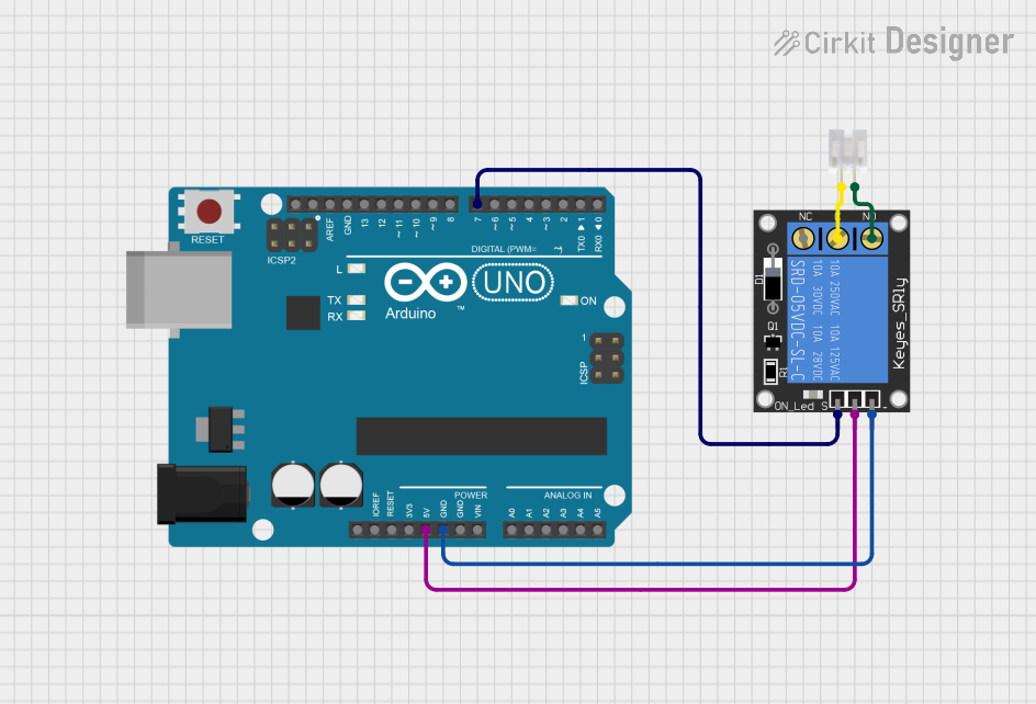
Example: Connecting to an Arduino UNO
While the LRD350 is not typically used with microcontrollers like the Arduino UNO, you can monitor its auxiliary contacts for trip status. Below is an example code snippet:
// Example code to monitor the LRD350 auxiliary contact with Arduino UNO
const int auxContactPin = 2;  // Pin connected to the NC auxiliary contact (95-96)
const int ledPin = 13;        // Built-in LED to indicate trip status

void setup() {
  pinMode(auxContactPin, INPUT_PULLUP); // Configure pin as input with pull-up resistor
  pinMode(ledPin, OUTPUT);             // Configure LED pin as output
}

void loop() {
  int contactState = digitalRead(auxContactPin); // Read the auxiliary contact state

  if (contactState == HIGH) {
    // Auxiliary contact is open, indicating a trip
    digitalWrite(ledPin, HIGH); // Turn on LED
  } else {
    // Auxiliary contact is closed, normal operation
    digitalWrite(ledPin, LOW);  // Turn off LED
  }

  delay(100); // Small delay for stability
}
Troubleshooting and FAQs
Common Issues and Solutions
Relay Does Not Trip During Overload:
- Cause: Incorrect current setting.
- Solution: Verify and adjust the current setting to match the motor's full load current.
Frequent Tripping:
- Cause: Overloaded motor or incorrect current setting.
- Solution: Check the motor load and ensure it is within the rated capacity. Adjust the relay setting if necessary.
Relay Fails to Reset:
- Cause: Persistent overload condition or damaged relay.
- Solution: Inspect the motor and wiring for faults. Replace the relay if it is damaged.
Auxiliary Contacts Not Functioning:
- Cause: Loose wiring or contact wear.
- Solution: Tighten connections and inspect the contacts for wear or damage.
FAQs
Q1: Can the LRD350 be used with single-phase motors?
A1: No, the LRD350 is designed for three-phase motors. For single-phase applications, use a suitable single-phase overload relay.
Q2: How do I know if the relay has tripped?
A2: The auxiliary contacts (95-96 and 97-98) change state when the relay trips. Additionally, the reset button may pop out.
Q3: Can I use the LRD350 with a motor starter?
A3: Yes, the LRD350 is designed to be mounted directly onto Schneider contactors, making it ideal for use with motor starters.
Q4: What is the difference between manual and automatic reset?
A4: In manual reset mode, the relay must be reset manually after a trip. In automatic reset mode, the relay resets itself once the overload condition is cleared.