How to Use Analof Rotation Sensor: Examples, Pinouts, and Specs
Introduction
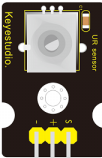
The Keyestudio Analog Rotation Sensor is a device designed to measure the angle of rotation and output a corresponding analog voltage signal. This sensor is widely used in robotics, automation, and other applications requiring precise position feedback. Its simple design and ease of use make it an excellent choice for both beginners and experienced engineers.
Explore Projects Built with Analof Rotation Sensor
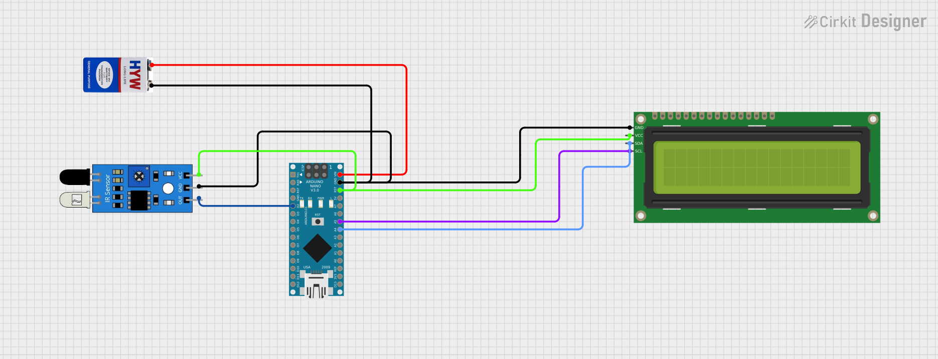
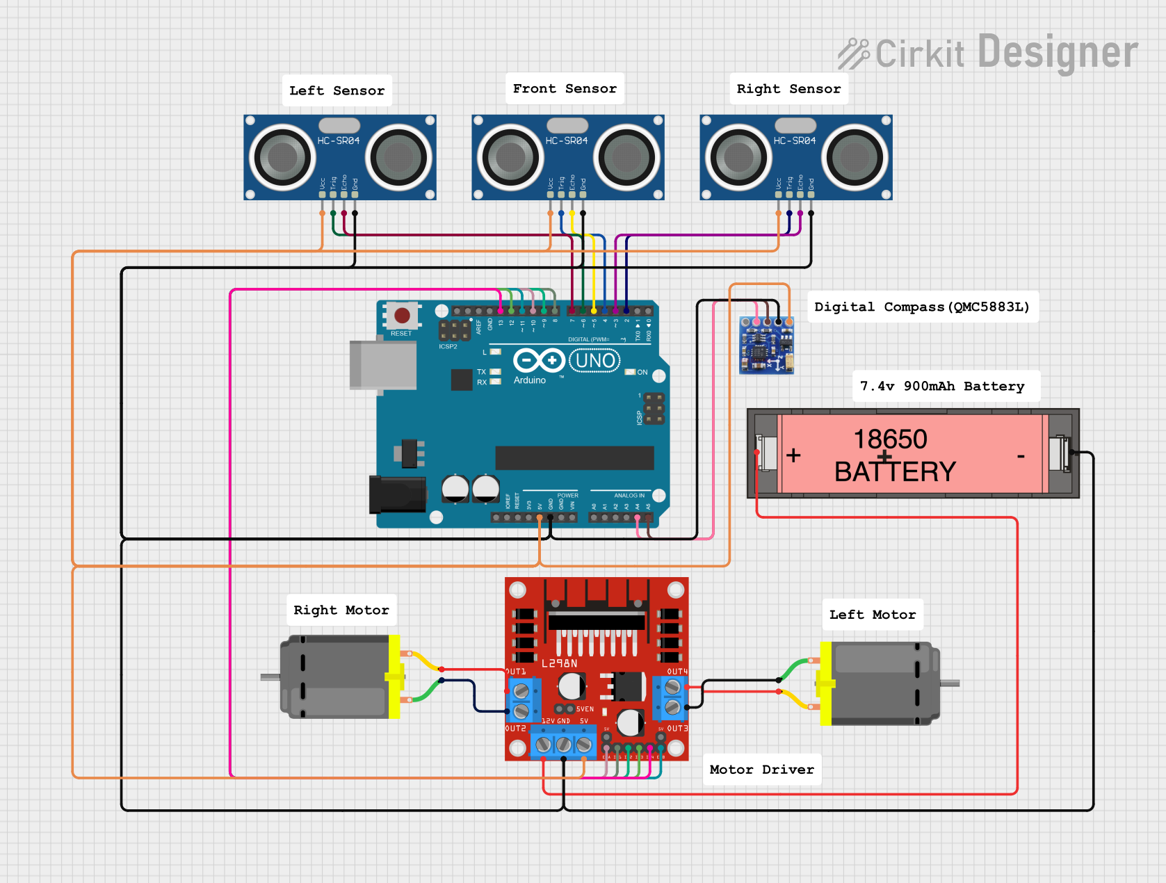
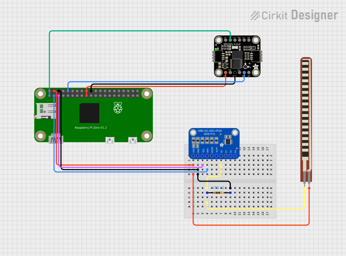
Explore Projects Built with Analof Rotation Sensor
Common Applications
- Position feedback in robotic arms and servo systems
- Angle measurement in automation systems
- User input devices such as dials and knobs
- Educational projects and prototyping
Technical Specifications
The following table outlines the key technical details of the Keyestudio Analog Rotation Sensor:
| Parameter | Specification |
|---|---|
| Operating Voltage | 3.3V - 5V |
| Output Signal | Analog voltage (0V to Vcc) |
| Measurement Range | 0° to 300° |
| Resolution | Continuous (depends on ADC of microcontroller) |
| Connector Type | 3-pin (GND, VCC, Signal) |
| Dimensions | 30mm x 20mm x 15mm |
Pin Configuration
The sensor has a 3-pin interface. The table below describes each pin:
| Pin | Name | Description |
|---|---|---|
| 1 | GND | Ground connection |
| 2 | VCC | Power supply (3.3V to 5V) |
| 3 | Signal | Analog output voltage proportional to rotation angle |
Usage Instructions
Connecting the Sensor
- Power the Sensor: Connect the
VCCpin to a 3.3V or 5V power source and theGNDpin to ground. - Read the Signal: Connect the
Signalpin to an analog input pin on your microcontroller (e.g., Arduino UNO). - Calibrate the Sensor: Rotate the sensor to its minimum and maximum positions to determine the corresponding voltage range.
Example Circuit
Below is an example of how to connect the Analog Rotation Sensor to an Arduino UNO:
- GND → GND on Arduino
- VCC → 5V on Arduino
- Signal → A0 (Analog Pin 0) on Arduino
Example Code
The following Arduino code reads the sensor's analog output and prints the corresponding angle to the Serial Monitor:
// Define the analog pin connected to the sensor
const int sensorPin = A0;

// Define the maximum rotation angle of the sensor
const int maxAngle = 300;

void setup() {
  // Initialize the Serial Monitor for debugging
  Serial.begin(9600);
}

void loop() {
  // Read the analog value from the sensor (0-1023)
  int sensorValue = analogRead(sensorPin);

  // Map the sensor value to the rotation angle (0-300 degrees)
  int angle = map(sensorValue, 0, 1023, 0, maxAngle);

  // Print the angle to the Serial Monitor
  Serial.print("Rotation Angle: ");
  Serial.print(angle);
  Serial.println(" degrees");

  // Add a short delay for stability
  delay(100);
}
Best Practices
- Ensure the sensor is powered within its operating voltage range (3.3V to 5V).
- Avoid applying excessive force to the rotating knob to prevent damage.
- Use a stable power supply to minimize noise in the analog output signal.
- If the sensor is used in a noisy environment, consider adding a capacitor between the
SignalandGNDpins to filter out noise.
Troubleshooting and FAQs
Common Issues
No Output Signal
- Cause: Incorrect wiring or loose connections.
- Solution: Double-check the connections to ensure the
VCC,GND, andSignalpins are properly connected.
Inconsistent Readings
- Cause: Electrical noise or unstable power supply.
- Solution: Use a decoupling capacitor (e.g., 0.1µF) between
VCCandGNDto stabilize the power supply.
Output Voltage Does Not Change
- Cause: Sensor is damaged or the knob is stuck.
- Solution: Inspect the sensor for physical damage and ensure the knob rotates freely.
FAQs
Q: Can this sensor be used with a 3.3V microcontroller like the ESP32?
A: Yes, the sensor operates within a voltage range of 3.3V to 5V, making it compatible with 3.3V microcontrollers.
Q: How do I increase the accuracy of the angle measurement?
A: Use a microcontroller with a higher-resolution ADC (e.g., 12-bit or 16-bit) to improve the precision of the analog-to-digital conversion.
Q: What is the lifespan of the sensor?
A: The sensor is designed for long-term use, but its lifespan depends on the frequency and intensity of use. Avoid excessive force to prolong its life.
Q: Can I use this sensor to measure continuous 360° rotation?
A: No, the sensor has a limited range of 0° to 300°. For continuous rotation, consider using an encoder instead.
By following this documentation, you can effectively integrate the Keyestudio Analog Rotation Sensor into your projects and troubleshoot any issues that arise.