Cirkit Designer Logo
Cirkit Designer
Your all-in-one circuit design IDE
Home / 
Component Documentation

How to Use MKE-S10 CNY70 Line Follower Sensor: Examples, Pinouts, and Specs

Image of MKE-S10 CNY70 Line Follower Sensor
Cirkit Designer LogoDesign with MKE-S10 CNY70 Line Follower Sensor in Cirkit Designer

Introduction

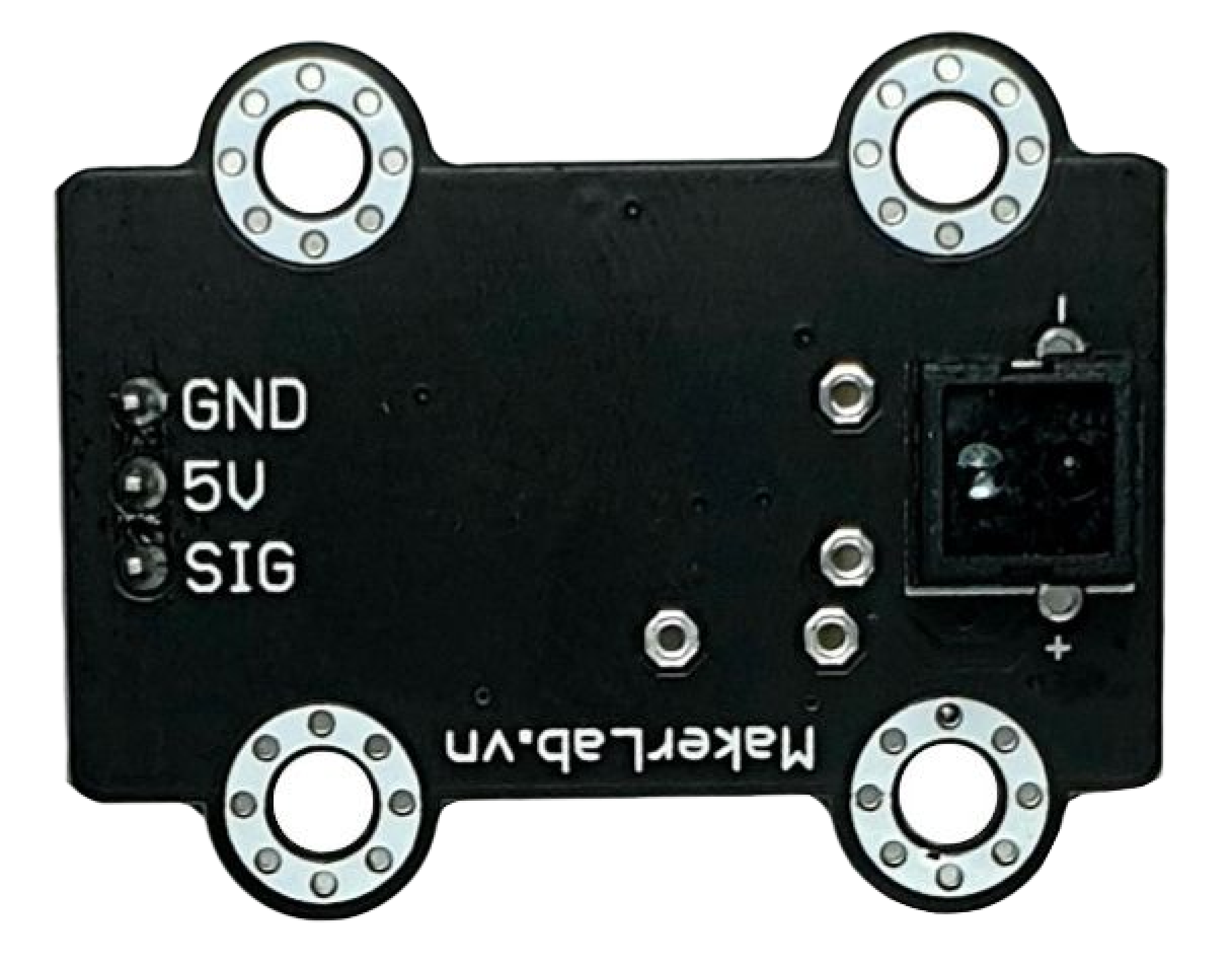
The MKE-S10 CNY70 is a compact line follower sensor designed for robotics and automation applications. It utilizes an infrared LED and a phototransistor to detect the contrast between a line (typically black) and the surrounding surface (typically white). This sensor is widely used in educational robots, maze solvers, and industrial line following vehicles.

Explore Projects Built with MKE-S10 CNY70 Line Follower Sensor

Use Cirkit Designer to design, explore, and prototype these projects online. Some projects support real-time simulation. Click "Open Project" to start designing instantly!
Battery-Powered Sumo Robot with IR Sensors and DC Motors
Image of MASSIVE SUMO AUTO BOARD: A project utilizing MKE-S10 CNY70 Line Follower Sensor in a practical application
This circuit is designed for a robotic system, featuring a Massive Sumo Board as the central controller. It integrates multiple FS-80NK diffuse IR sensors and IR line sensors for obstacle detection and line following, respectively, and controls two GM25 DC motors via MD13s motor drivers for movement. Power is supplied by an 11.1V LiPo battery.
Cirkit Designer LogoOpen Project in Cirkit Designer
MakerEdu Creator with Bluetooth, IR Sensors, LCD Display, and Push Button Interaction
Image of MKL Distance Measurement: A project utilizing MKE-S10 CNY70 Line Follower Sensor in a practical application
This circuit features a MakerEdu Creator microcontroller board interfaced with two MKE-S11 IR Infrared Obstacle Avoidance Sensors, a MKE-M02 Push Button Tact Switch, a MKE-M15 Bluetooth module, and a MKE-M08 LCD2004 I2C display module. The push button is connected to a digital input for user interaction, while the IR sensors are likely used for detecting obstacles. The Bluetooth module enables wireless communication, and the LCD display provides a user interface for displaying information or statuses.
Cirkit Designer LogoOpen Project in Cirkit Designer
Raspberry Pi Zero W Based Line Tracking and Obstacle Detection System
Image of CSC615-Assignment#4-LineSensor: A project utilizing MKE-S10 CNY70 Line Follower Sensor in a practical application
This circuit integrates a Raspberry Pi Zero W with two sensors: a KY-033 Line Tracking Sensor and an FC-51 IR Sensor. The Raspberry Pi is configured to receive digital input signals from the KY-033 sensor on GPIO 04 and from the FC-51 sensor on GPIO 24. The circuit is designed for object detection and line tracking applications, with the Raspberry Pi processing the sensor inputs for decision-making tasks.
Cirkit Designer LogoOpen Project in Cirkit Designer
Battery-Powered Line Following Robot with IR Sensors and Cytron URC10 Motor Controller
Image of URC10 SUMO AUTO: A project utilizing MKE-S10 CNY70 Line Follower Sensor in a practical application
This circuit is a robotic control system that uses multiple IR sensors for line detection and obstacle avoidance, powered by a 3S LiPo battery. The Cytron URC10 motor driver, controlled by a microcontroller, drives two GM25 DC motors based on input from the sensors and a rocker switch, with a 7-segment panel voltmeter displaying the battery voltage.
Cirkit Designer LogoOpen Project in Cirkit Designer

Explore Projects Built with MKE-S10 CNY70 Line Follower Sensor

Use Cirkit Designer to design, explore, and prototype these projects online. Some projects support real-time simulation. Click "Open Project" to start designing instantly!
Image of MASSIVE SUMO AUTO BOARD: A project utilizing MKE-S10 CNY70 Line Follower Sensor in a practical application
Battery-Powered Sumo Robot with IR Sensors and DC Motors
This circuit is designed for a robotic system, featuring a Massive Sumo Board as the central controller. It integrates multiple FS-80NK diffuse IR sensors and IR line sensors for obstacle detection and line following, respectively, and controls two GM25 DC motors via MD13s motor drivers for movement. Power is supplied by an 11.1V LiPo battery.
Cirkit Designer LogoOpen Project in Cirkit Designer
Image of MKL Distance Measurement: A project utilizing MKE-S10 CNY70 Line Follower Sensor in a practical application
MakerEdu Creator with Bluetooth, IR Sensors, LCD Display, and Push Button Interaction
This circuit features a MakerEdu Creator microcontroller board interfaced with two MKE-S11 IR Infrared Obstacle Avoidance Sensors, a MKE-M02 Push Button Tact Switch, a MKE-M15 Bluetooth module, and a MKE-M08 LCD2004 I2C display module. The push button is connected to a digital input for user interaction, while the IR sensors are likely used for detecting obstacles. The Bluetooth module enables wireless communication, and the LCD display provides a user interface for displaying information or statuses.
Cirkit Designer LogoOpen Project in Cirkit Designer
Image of CSC615-Assignment#4-LineSensor: A project utilizing MKE-S10 CNY70 Line Follower Sensor in a practical application
Raspberry Pi Zero W Based Line Tracking and Obstacle Detection System
This circuit integrates a Raspberry Pi Zero W with two sensors: a KY-033 Line Tracking Sensor and an FC-51 IR Sensor. The Raspberry Pi is configured to receive digital input signals from the KY-033 sensor on GPIO 04 and from the FC-51 sensor on GPIO 24. The circuit is designed for object detection and line tracking applications, with the Raspberry Pi processing the sensor inputs for decision-making tasks.
Cirkit Designer LogoOpen Project in Cirkit Designer
Image of URC10 SUMO AUTO: A project utilizing MKE-S10 CNY70 Line Follower Sensor in a practical application
Battery-Powered Line Following Robot with IR Sensors and Cytron URC10 Motor Controller
This circuit is a robotic control system that uses multiple IR sensors for line detection and obstacle avoidance, powered by a 3S LiPo battery. The Cytron URC10 motor driver, controlled by a microcontroller, drives two GM25 DC motors based on input from the sensors and a rocker switch, with a 7-segment panel voltmeter displaying the battery voltage.
Cirkit Designer LogoOpen Project in Cirkit Designer

Common Applications and Use Cases

  • Educational robotics kits
  • Automated guided vehicles (AGVs)
  • Line following robots for competitions
  • Position sensing in industrial automation

Technical Specifications

Key Technical Details

  • Operating Voltage: 4.5V to 5.5V
  • Current Consumption: 50mA (typical)
  • Output Type: Analog voltage
  • Peak Operating Distance: 0.5mm to 15mm
  • Wavelength: 950nm (Infrared)

Pin Configuration and Descriptions

Pin Number Name Description
1 VCC Power supply (4.5V to 5.5V)
2 GND Ground
3 VO Analog voltage output relative to surface reflectivity

Usage Instructions

How to Use the Component in a Circuit

  1. Power Supply: Connect the VCC pin to a 5V power supply and the GND pin to the ground.
  2. Output Signal: Connect the VO pin to an analog input on your microcontroller to read the sensor's output.
  3. Mounting: Position the sensor close to the surface to ensure accurate detection. The recommended distance is within the peak operating range of 0.5mm to 15mm.

Important Considerations and Best Practices

  • Surface Contrast: Ensure a high contrast between the line and the surrounding surface for optimal performance.
  • Ambient Light: Shield the sensor from direct sunlight and other sources of infrared light to prevent interference.
  • Calibration: Calibrate the sensor for the specific surface and line color used in your application.
  • Voltage Levels: When interfacing with microcontrollers operating at lower voltages (e.g., 3.3V), use a voltage divider or level shifter for the sensor's output.

Example Code for Arduino UNO

// Define the pin connected to the sensor's output
const int sensorPin = A0;

void setup() {
  // Initialize serial communication at 9600 baud rate
  Serial.begin(9600);
}

void loop() {
  // Read the analog value from the sensor
  int sensorValue = analogRead(sensorPin);
  
  // Convert the analog value to a voltage (0-5V)
  float voltage = sensorValue * (5.0 / 1023.0);
  
  // Print the voltage to the Serial Monitor
  Serial.println(voltage);
  
  // Delay for a short period to avoid spamming the Serial Monitor
  delay(100);
}

Troubleshooting and FAQs

Common Issues Users Might Face

  • Inconsistent Readings: If the sensor provides inconsistent readings, check for proper alignment and distance from the surface. Also, verify that the surface contrast is sufficient.
  • No Output: Ensure that the sensor is correctly powered and that all connections are secure. Check the VCC and GND pins for proper voltage levels.
  • Interference from Ambient Light: If ambient light is affecting the sensor's performance, try adding a physical shield around the sensor to block out extraneous light.

Solutions and Tips for Troubleshooting

  • Calibration: Adjust the threshold in your code to match the specific reflectivity of the line and surface.
  • Wiring Check: Double-check all connections, especially if the sensor is not responding or behaving erratically.
  • Sensor Cleaning: Keep the sensor clean and free from dust or debris that could obstruct the infrared signal.

FAQs

Q: Can the MKE-S10 CNY70 sensor detect colors other than black and white? A: The sensor is designed to detect reflectivity differences. While optimized for black and white, it can detect other colors if there is sufficient contrast.

Q: What is the maximum operating distance of the sensor? A: The sensor operates best within a range of 0.5mm to 15mm from the surface.

Q: How can I adjust the sensitivity of the sensor? A: Sensitivity can be adjusted by calibrating the threshold value in your code based on the analog voltage readings from the sensor.

Q: Is it possible to use multiple MKE-S10 CNY70 sensors on a single robot? A: Yes, you can use multiple sensors to improve line detection and navigation accuracy. Ensure each sensor is connected to a separate analog input pin on your microcontroller.