
How to Use MCP42xxx: Examples, Pinouts, and Specs
 Design with MCP42xxx in Cirkit Designer
Introduction
The MCP42xxx is a family of dual-channel digital potentiometers manufactured by Microchip Technology. These devices are controlled via an SPI (Serial Peripheral Interface) and are designed to provide precise resistance adjustments in electronic circuits. Each channel operates as a variable resistor or a voltage divider, making the MCP42xxx ideal for applications requiring fine-tuned control of voltage or current.
Explore Projects Built with MCP42xxx
 Open Project in Cirkit Designer
 Open Project in Cirkit Designer
 Open Project in Cirkit Designer
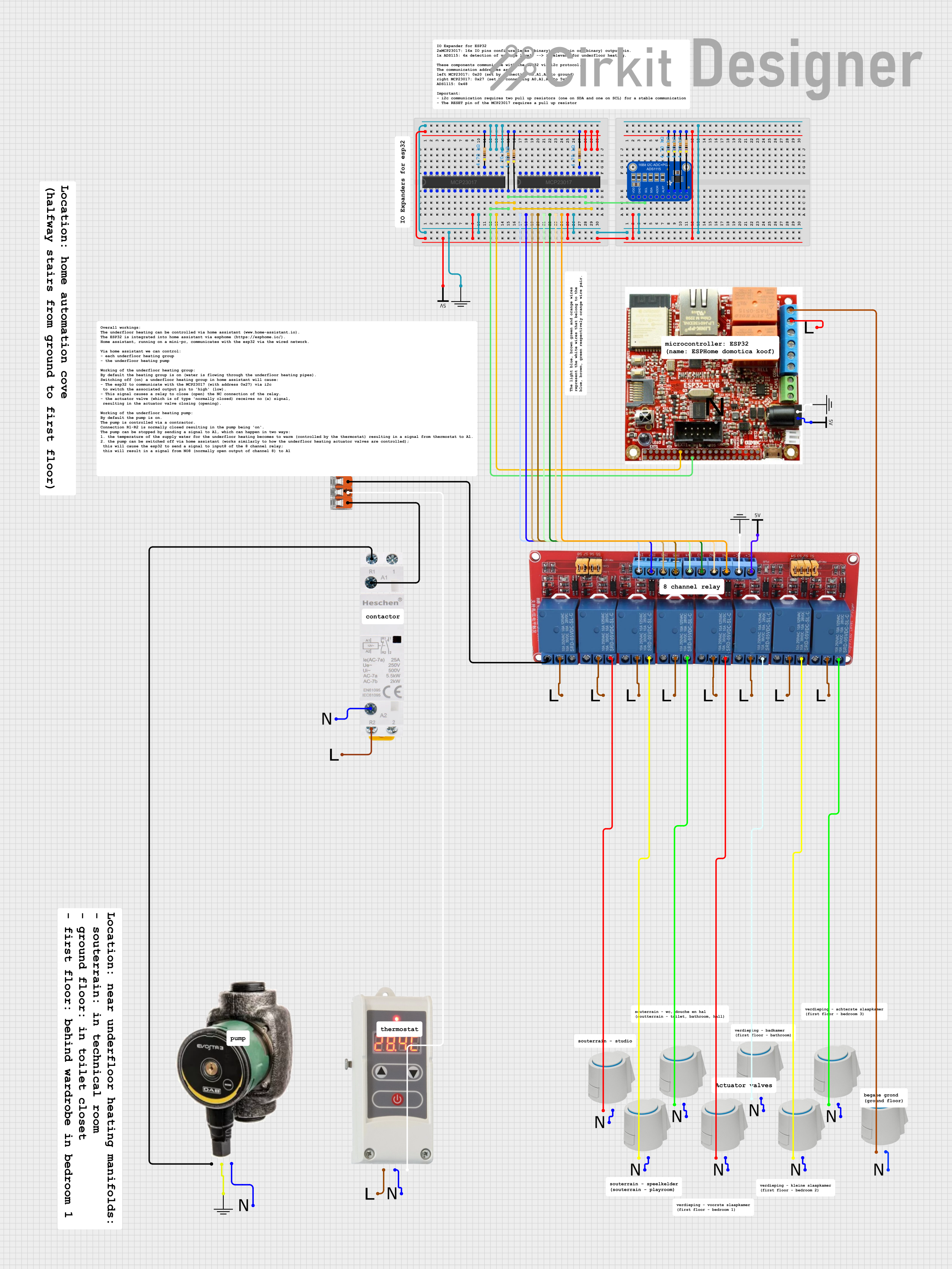 Open Project in Cirkit Designer
Explore Projects Built with MCP42xxx
Open Project in Cirkit DesignerOpen Project in Cirkit DesignerOpen Project in Cirkit DesignerOpen Project in Cirkit DesignerCommon Applications
- Audio volume control
- LED brightness adjustment
- Sensor calibration
- Programmable gain amplifiers
- Adjustable power supplies
- Signal conditioning
Technical Specifications
The MCP42xxx family includes several variants (e.g., MCP42010, MCP42050, MCP42100) that differ in their resistance values. Below are the general specifications:
| Parameter | Value |
|---|---|
| Supply Voltage (VDD) | 2.7V to 5.5V |
| Resistance Options | 10 kΩ, 50 kΩ, 100 kΩ |
| Number of Channels | 2 |
| Resolution | 8 bits (256 steps) |
| Communication Interface | SPI |
| Operating Temperature Range | -40°C to +125°C |
| Wiper Current (Max) | ±1 mA |
| End-to-End Resistance Tolerance | ±20% |
| Non-Volatile Memory | No |
Pin Configuration and Descriptions
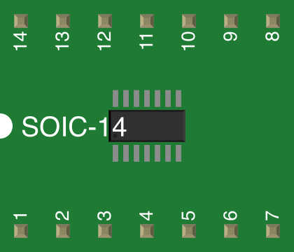
The MCP42xxx is typically available in an 8-pin PDIP, SOIC, or TSSOP package. Below is the pinout description:
| Pin | Name | Description |
|---|---|---|
| 1 | CS | Chip Select (active low). Enables SPI communication when pulled low. |
| 2 | SCK | Serial Clock. Synchronizes data transfer during SPI communication. |
| 3 | SDI | Serial Data Input. Receives data from the microcontroller. |
| 4 | VSS | Ground reference for the device. |
| 5 | PW0 | Wiper terminal for potentiometer 0. |
| 6 | PW1 | Wiper terminal for potentiometer 1. |
| 7 | VDD | Positive supply voltage. |
| 8 | SDO | Serial Data Output. Sends data back to the microcontroller (optional, daisy-chain). |
Usage Instructions
How to Use the MCP42xxx in a Circuit
- Power Supply: Connect the VDD pin to a 2.7V–5.5V power source and the VSS pin to ground.
- SPI Connections:
- Connect the CS pin to a GPIO pin on the microcontroller to enable/disable communication.
- Connect the SCK pin to the SPI clock pin of the microcontroller.
- Connect the SDI pin to the SPI MOSI (Master Out Slave In) pin of the microcontroller.
- Optionally, connect the SDO pin to the SPI MISO (Master In Slave Out) pin for daisy-chaining multiple devices.
- Potentiometer Terminals:
- Connect the PW0 and PW1 pins to the circuit where variable resistance is required.
- The wiper position is controlled via SPI commands.
Important Considerations
- SPI Configuration: The MCP42xxx operates in SPI Mode 0 (CPOL = 0, CPHA = 0). Ensure the microcontroller's SPI settings match this mode.
- Wiper Current: Avoid exceeding the maximum wiper current of ±1 mA to prevent damage.
- Power-On State: The wiper positions default to mid-scale (128/256) on power-up.
- Daisy-Chaining: Multiple MCP42xxx devices can be daisy-chained by connecting the SDO pin of one device to the SDI pin of the next.
Example Code for Arduino UNO
Below is an example of how to control the MCP42xxx using an Arduino UNO:
#include <SPI.h>

// Define MCP42xxx pins
const int CS_PIN = 10; // Chip Select pin connected to Arduino pin 10

void setup() {
  // Initialize SPI communication
  SPI.begin();
  pinMode(CS_PIN, OUTPUT);
  digitalWrite(CS_PIN, HIGH); // Ensure CS is initially high
}

void loop() {
  // Set potentiometer 0 to a specific wiper position (e.g., 128/256)
  setPotentiometer(0, 128);
  delay(1000); // Wait for 1 second

  // Set potentiometer 1 to a different wiper position (e.g., 64/256)
  setPotentiometer(1, 64);
  delay(1000); // Wait for 1 second
}

// Function to set the wiper position of a potentiometer
void setPotentiometer(byte potNumber, byte value) {
  digitalWrite(CS_PIN, LOW); // Enable SPI communication

  // Send command byte: 0x10 for pot 0, 0x11 for pot 1
  SPI.transfer(0x10 | (potNumber & 0x01));
  SPI.transfer(value); // Send wiper position (0-255)

  digitalWrite(CS_PIN, HIGH); // Disable SPI communication
}
Notes:
- Replace
CS_PINwith the actual pin connected to the MCP42xxx's CS pin. - The
setPotentiometerfunction allows you to control each potentiometer independently.
Troubleshooting and FAQs
Common Issues
No Response from the MCP42xxx:
- Ensure the CS pin is pulled low during SPI communication.
- Verify the SPI clock and data connections.
- Check that the SPI mode is set to Mode 0 (CPOL = 0, CPHA = 0).
Incorrect Wiper Position:
- Confirm that the value sent to the MCP42xxx is within the valid range (0–255).
- Check for noise or interference on the SPI lines.
Device Overheating:
- Ensure the wiper current does not exceed ±1 mA.
- Verify that the supply voltage is within the specified range (2.7V–5.5V).
Daisy-Chaining Issues:
- Ensure the SDO pin of one device is correctly connected to the SDI pin of the next.
- Verify that the SPI commands are sent in the correct sequence.
FAQs
Q: Can the MCP42xxx store wiper positions after power-off?
A: No, the MCP42xxx does not have non-volatile memory. The wiper positions reset to mid-scale on power-up.
Q: What is the maximum number of devices that can be daisy-chained?
A: The maximum number depends on the SPI clock speed and the total capacitance of the SPI bus. Typically, up to 8 devices can be daisy-chained without issues.
Q: Can I use the MCP42xxx with a 3.3V microcontroller?
A: Yes, the MCP42xxx operates with supply voltages as low as 2.7V, making it compatible with 3.3V systems.
Q: How do I calculate the resistance at the wiper?
A: The resistance is proportional to the wiper position:
( R_{wiper} = \frac{\text{Wiper Position}}{256} \times R_{total} )
where ( R_{total} ) is the end-to-end resistance of the potentiometer (e.g., 10 kΩ, 50 kΩ, or 100 kΩ).