How to Use 2 Channel 30A AC Relay 5V DC Control: Examples, Pinouts, and Specs
2 Channel 30A AC Relay 5V DC Control - Documentation
1. Introduction
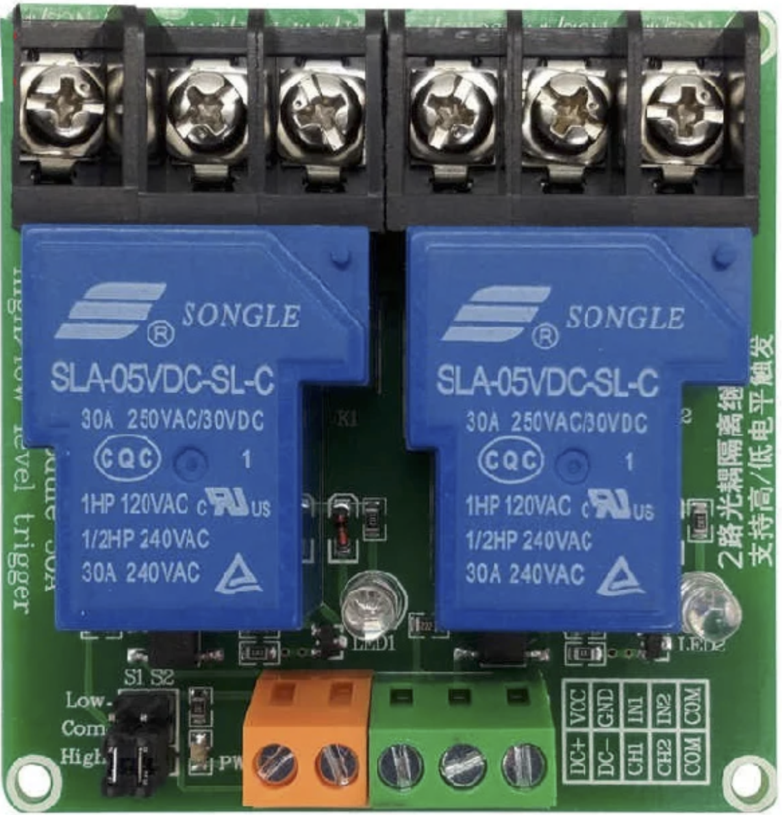
The 2 Channel 30A AC Relay 5V DC Control is a versatile relay module designed to control high-voltage AC devices using a low-voltage DC signal. This module features two independent relay channels, each capable of switching up to 30A of current, making it ideal for applications requiring high-power switching. The module operates on a 5V DC control signal, making it compatible with microcontrollers like Arduino, Raspberry Pi, and other logic-level devices.
Common Applications
- Home Automation: Control lights, fans, and other household appliances.
- Industrial Automation: Operate motors, pumps, and other high-power equipment.
- IoT Projects: Enable remote control of AC devices via microcontrollers or IoT platforms.
- Robotics: Power high-current actuators or motors.
- Smart Energy Systems: Automate energy-saving devices or systems.
2. Technical Specifications
Key Technical Details
| Parameter | Specification |
|---|---|
| Operating Voltage | 5V DC |
| Relay Channels | 2 |
| Maximum Switching Current | 30A per channel |
| Maximum Switching Voltage | 250V AC / 30V DC |
| Control Signal Voltage | 3.3V to 5V DC (logic-level compatible) |
| Trigger Type | Active Low |
| Isolation | Optocoupler isolation for signal safety |
| Dimensions | ~50mm x 50mm x 20mm |
| Mounting Holes | Yes (for secure installation) |
Pin Configuration and Descriptions
Input Side (Control Pins)
| Pin | Label | Description |
|---|---|---|
| 1 | VCC | Connect to 5V DC power supply (logic-level voltage). |
| 2 | GND | Connect to ground of the power supply or microcontroller. |
| 3 | IN1 | Control signal for Relay 1 (Active Low). |
| 4 | IN2 | Control signal for Relay 2 (Active Low). |
Output Side (Relay Terminals)
Each relay channel has three terminals:
| Terminal | Label | Description |
|---|---|---|
| 1 | COM | Common terminal for the relay. |
| 2 | NO | Normally Open terminal. Connect the load here for default OFF state. |
| 3 | NC | Normally Closed terminal. Connect the load here for default ON state. |
3. Usage Instructions
Connecting the Relay Module
Power the Module:
- Connect the VCC pin to a 5V DC power supply.
- Connect the GND pin to the ground of the power supply or microcontroller.
Control Signals:
- Connect the IN1 and IN2 pins to the digital output pins of your microcontroller.
- Ensure the control signal is Active Low (i.e., sending a LOW signal will activate the relay).
Load Connections:
- For each relay channel, connect the load to the COM and either NO or NC terminals:
- Use NO if the load should be OFF by default and turn ON when the relay is activated.
- Use NC if the load should be ON by default and turn OFF when the relay is activated.
- For each relay channel, connect the load to the COM and either NO or NC terminals:
Example Circuit
- Microcontroller: Arduino UNO
- Load: AC light bulb (controlled by Relay 1)
Wiring Diagram
- Connect VCC and GND of the relay module to the Arduino's 5V and GND pins.
- Connect IN1 to Arduino digital pin 7.
- Connect the AC light bulb to the COM and NO terminals of Relay 1.
- Ensure the AC power source is properly connected to the relay's terminals.
4. Arduino Example Code
Below is an example Arduino sketch to control the relay module:
// Define the control pins for the relay module
#define RELAY1_PIN 7  // Relay 1 control pin
#define RELAY2_PIN 8  // Relay 2 control pin

void setup() {
  // Set relay pins as outputs
  pinMode(RELAY1_PIN, OUTPUT);
  pinMode(RELAY2_PIN, OUTPUT);

  // Initialize relays to OFF state (HIGH signal for Active Low logic)
  digitalWrite(RELAY1_PIN, HIGH);
  digitalWrite(RELAY2_PIN, HIGH);
}

void loop() {
  // Turn Relay 1 ON (Active Low)
  digitalWrite(RELAY1_PIN, LOW);
  delay(5000); // Keep Relay 1 ON for 5 seconds

  // Turn Relay 1 OFF
  digitalWrite(RELAY1_PIN, HIGH);
  delay(2000); // Wait for 2 seconds

  // Turn Relay 2 ON (Active Low)
  digitalWrite(RELAY2_PIN, LOW);
  delay(5000); // Keep Relay 2 ON for 5 seconds

  // Turn Relay 2 OFF
  digitalWrite(RELAY2_PIN, HIGH);
  delay(2000); // Wait for 2 seconds
}
Code Explanation
- The relays are controlled using digital pins 7 and 8.
- The relays are initialized to the OFF state by sending a HIGH signal (Active Low logic).
- The loop alternates between turning Relay 1 and Relay 2 ON and OFF with delays.
5. Troubleshooting and FAQs
Common Issues and Solutions
| Issue | Possible Cause | Solution |
|---|---|---|
| Relay does not activate | Insufficient power supply to the module | Ensure the module is powered with a stable 5V DC supply. |
| Relay activates but load does not work | Incorrect wiring of load terminals | Verify the load is connected to the correct COM and NO/NC terminals. |
| Microcontroller cannot control the relay | Signal voltage mismatch | Ensure the control signal is 3.3V-5V DC and matches the relay's requirements. |
| Relay remains ON or OFF unexpectedly | Noise or interference in the control signal | Use a pull-up or pull-down resistor on the control pins to stabilize signals. |
FAQs
Can I use this relay module with a 3.3V microcontroller?
- Yes, the module is compatible with 3.3V control signals, but ensure the power supply to the module is 5V DC.
What precautions should I take when switching high-voltage AC loads?
- Always ensure proper insulation and avoid touching the relay terminals while the circuit is powered.
- Use a fuse or circuit breaker for safety.
Can I control DC loads with this relay?
- Yes, the relay can switch DC loads up to 30V DC and 30A.
How do I know if the relay is active?
- The module has onboard indicator LEDs that light up when the corresponding relay is activated.
This documentation provides a comprehensive guide to using the 2 Channel 30A AC Relay 5V DC Control module. By following the instructions and best practices outlined here, you can safely and effectively integrate this relay module into your projects.
Explore Projects Built with 2 Channel 30A AC Relay 5V DC Control

Explore Projects Built with 2 Channel 30A AC Relay 5V DC Control