How to Use BN-880 GPS: Examples, Pinouts, and Specs
Introduction
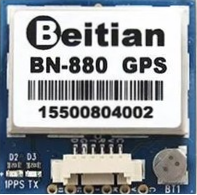
The BN-880 GPS is a high-performance GPS module designed to provide accurate and reliable positioning data. It features a built-in ceramic antenna, low power consumption, and supports multiple communication protocols, including UART and I2C. The module also includes a 3-axis gyroscope and accelerometer, making it ideal for applications requiring both positioning and orientation data.
Common applications of the BN-880 GPS include:
- Navigation systems for drones, vehicles, and boats
- Robotics requiring precise location and orientation
- IoT devices for geolocation tracking
- Outdoor mapping and surveying tools
Explore Projects Built with BN-880 GPS


Explore Projects Built with BN-880 GPS
Technical Specifications
The BN-880 GPS module is equipped with advanced features to ensure high accuracy and versatility. Below are its key technical details:
General Specifications
| Parameter | Value |
|---|---|
| GPS Chipset | u-blox NEO-M8N |
| Communication Protocols | UART, I2C |
| Operating Voltage | 3.3V to 5V |
| Power Consumption | ~45mA (active mode) |
| Positioning Accuracy | 2.5 meters CEP |
| Update Rate | Up to 10 Hz |
| Antenna Type | Built-in ceramic antenna |
| Dimensions | 36mm x 36mm x 8mm |
Pin Configuration
The BN-880 GPS module has a 6-pin interface for easy integration into circuits. Below is the pinout description:
| Pin Number | Pin Name | Description |
|---|---|---|
| 1 | VCC | Power supply input (3.3V to 5V) |
| 2 | GND | Ground connection |
| 3 | TX | UART Transmit (data output from GPS module) |
| 4 | RX | UART Receive (data input to GPS module) |
| 5 | SDA | I2C Data Line |
| 6 | SCL | I2C Clock Line |
Usage Instructions
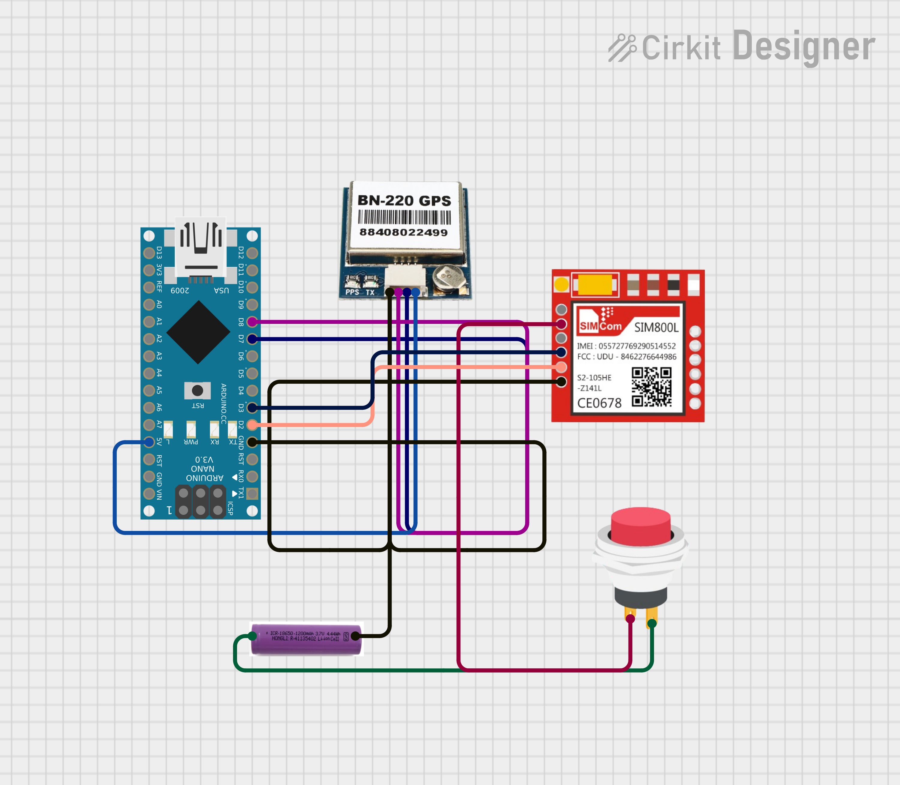
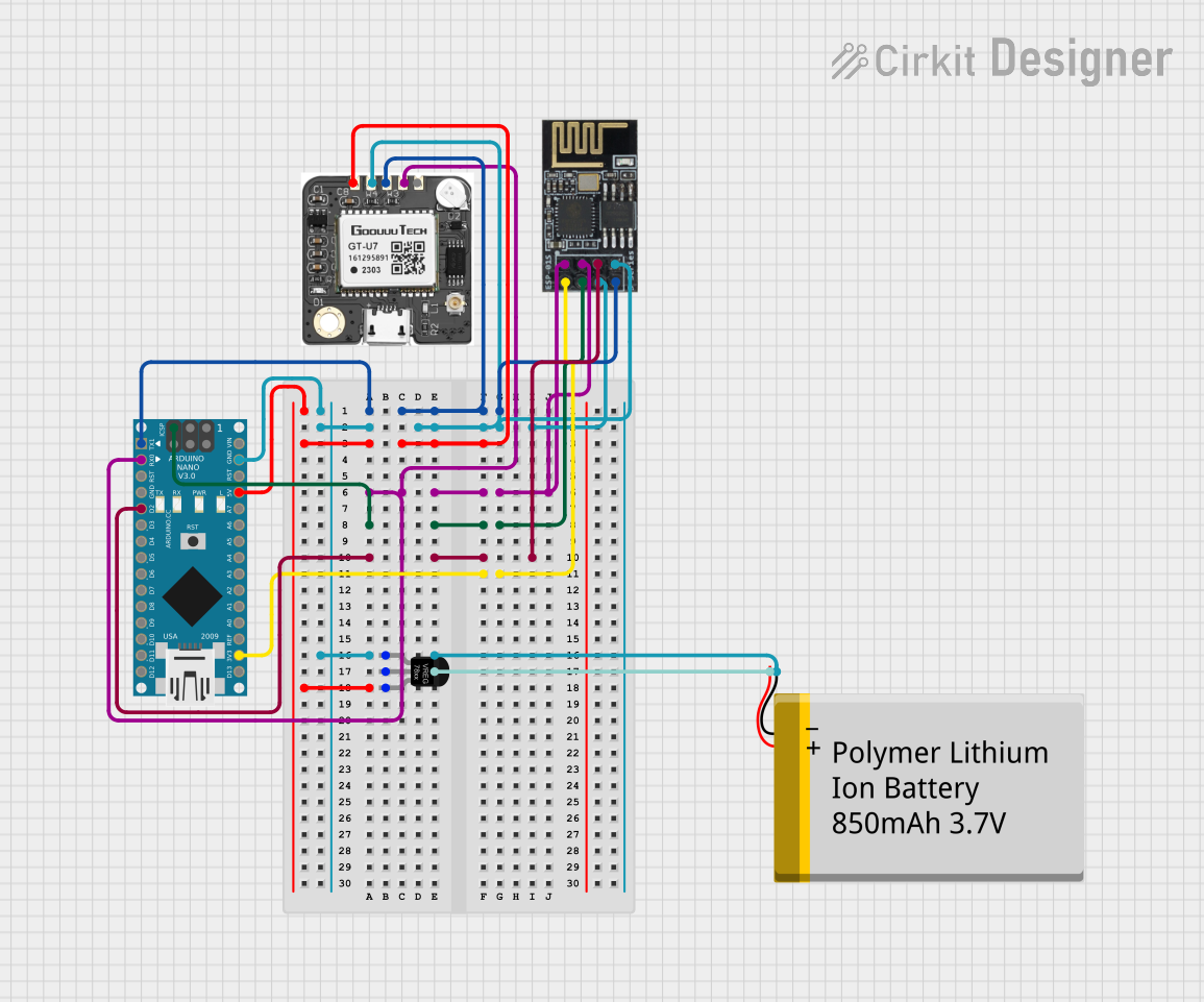
Connecting the BN-880 GPS to an Arduino UNO
To use the BN-880 GPS module with an Arduino UNO, follow these steps:
Wiring: Connect the module to the Arduino as shown below:
- VCC → 5V on Arduino
- GND → GND on Arduino
- TX → Pin 4 on Arduino (for software serial communication)
- RX → Pin 3 on Arduino (for software serial communication)
Install Required Libraries: Install the
TinyGPS++library in the Arduino IDE for parsing GPS data. Go to Sketch > Include Library > Manage Libraries, search forTinyGPS++, and install it.Upload Code: Use the following example code to read and display GPS data on the Serial Monitor.
#include <TinyGPS++.h>
#include <SoftwareSerial.h>

// Create a TinyGPS++ object to parse GPS data
TinyGPSPlus gps;

// Define software serial pins for GPS communication
SoftwareSerial gpsSerial(4, 3); // RX, TX

void setup() {
  Serial.begin(9600);          // Initialize Serial Monitor
  gpsSerial.begin(9600);       // Initialize GPS module communication
  Serial.println("BN-880 GPS Module Test");
}

void loop() {
  // Read data from the GPS module
  while (gpsSerial.available() > 0) {
    char c = gpsSerial.read();
    // Feed the data into the TinyGPS++ library
    if (gps.encode(c)) {
      // If a valid GPS sentence is received, display data
      if (gps.location.isUpdated()) {
        Serial.print("Latitude: ");
        Serial.print(gps.location.lat(), 6); // Print latitude
        Serial.print(", Longitude: ");
        Serial.println(gps.location.lng(), 6); // Print longitude
      }
    }
  }
}
Important Considerations
- Ensure the module has a clear view of the sky for optimal GPS signal reception.
- Avoid placing the module near sources of electromagnetic interference (e.g., motors, power supplies).
- Use a stable power supply to prevent voltage fluctuations that may affect performance.
- If using I2C communication, ensure the Arduino supports the required pull-up resistors on the SDA and SCL lines.
Troubleshooting and FAQs
Common Issues and Solutions
No GPS Data Received:
- Ensure the module is powered correctly (3.3V to 5V).
- Verify the TX and RX connections are not swapped.
- Check for a clear view of the sky to acquire satellite signals.
Incorrect or Inconsistent Data:
- Wait for the module to achieve a full GPS lock (may take a few minutes).
- Ensure the baud rate in the code matches the module's default baud rate (9600).
Arduino Freezes or Crashes:
- Ensure the software serial pins (RX/TX) are not used for other purposes.
- Avoid using the hardware Serial (pins 0 and 1) for GPS communication, as it may conflict with the Serial Monitor.
FAQs
Q: Can the BN-880 GPS module work indoors?
A: While the module may work indoors, GPS signal strength is significantly reduced. For best results, use the module outdoors with a clear view of the sky.
Q: How do I increase the update rate of the GPS module?
A: The update rate can be configured using u-blox's u-center software. Connect the module to a PC via a USB-to-TTL adapter and use the software to adjust settings.
Q: Can I use the BN-880 GPS with a Raspberry Pi?
A: Yes, the module can be connected to a Raspberry Pi via UART or I2C. Use libraries like gpsd or pyserial to interface with the module.
Q: What is the purpose of the built-in gyroscope and accelerometer?
A: The gyroscope and accelerometer provide orientation and motion data, which can be useful for applications like drones and robotics.
By following this documentation, you can effectively integrate and use the BN-880 GPS module in your projects.