How to Use Seeed Studio A603 Carrier board for Nvidia Jetson Nano: Examples, Pinouts, and Specs
Introduction
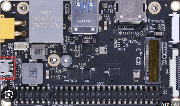
The Seeed Studio A603 Carrier Board is a versatile and compact platform designed specifically for the Nvidia Jetson Nano. It provides essential interfaces and connectivity options, making it an ideal choice for development, prototyping, and deployment of AI and machine learning applications. With support for GPIO, USB, HDMI, and power management, the A603 carrier board simplifies the integration of peripherals and accelerates project development.
Explore Projects Built with Seeed Studio A603 Carrier board for Nvidia Jetson Nano
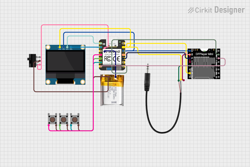

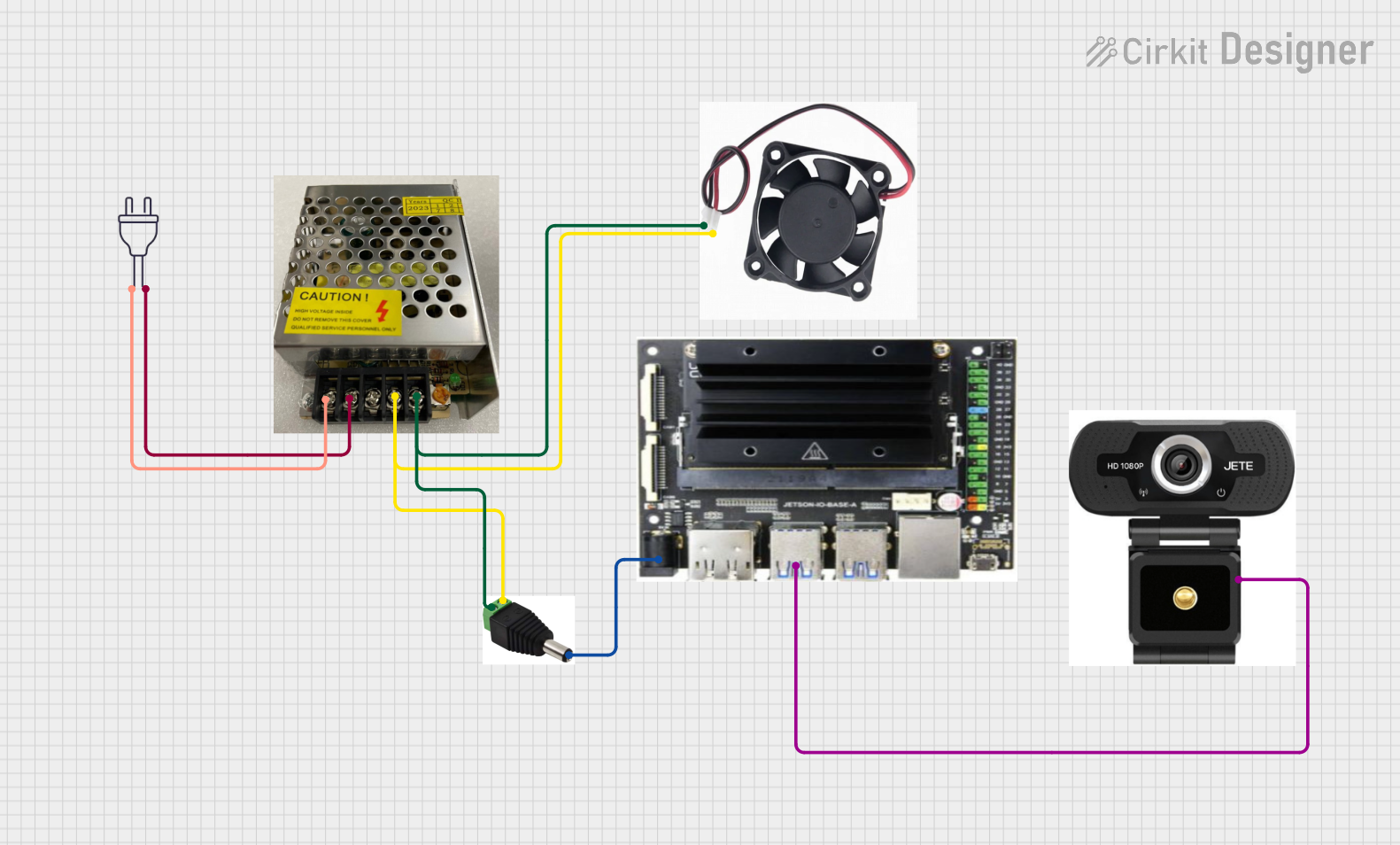
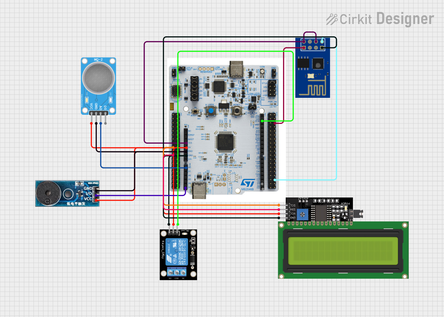
Explore Projects Built with Seeed Studio A603 Carrier board for Nvidia Jetson Nano
Common Applications and Use Cases
- AI and machine learning prototyping
- Robotics and autonomous systems
- IoT edge computing
- Smart surveillance systems
- Industrial automation and control
- Educational and research projects
Technical Specifications
Key Technical Details
| Specification | Details |
|---|---|
| Compatible Module | Nvidia Jetson Nano |
| Power Input | 5V DC (via USB-C or GPIO header) |
| USB Ports | 4x USB 3.0 Type-A |
| HDMI Output | 1x HDMI 2.0 |
| GPIO Header | 40-pin GPIO (Raspberry Pi-compatible layout) |
| Ethernet | 1x Gigabit Ethernet port |
| Camera Interface | 1x MIPI CSI-2 |
| Storage | MicroSD card slot |
| Dimensions | 100mm x 80mm |
Pin Configuration and Descriptions
The A603 carrier board features a 40-pin GPIO header compatible with the Raspberry Pi layout. Below is the pinout description:
| Pin Number | Pin Name | Functionality | Voltage Level |
|---|---|---|---|
| 1 | 3.3V | Power Output | 3.3V |
| 2 | 5V | Power Output | 5V |
| 3 | GPIO2 (SDA) | I2C Data | 3.3V |
| 4 | 5V | Power Output | 5V |
| 5 | GPIO3 (SCL) | I2C Clock | 3.3V |
| 6 | GND | Ground | 0V |
| 7 | GPIO4 | General Purpose I/O | 3.3V |
| 8 | GPIO14 (TXD) | UART Transmit | 3.3V |
| 9 | GND | Ground | 0V |
| 10 | GPIO15 (RXD) | UART Receive | 3.3V |
| ... | ... | ... | ... |
For the full GPIO pinout, refer to the official documentation provided by Seeed Studio.
Usage Instructions
How to Use the Component in a Circuit
Powering the Board:
- Connect a 5V DC power supply via the USB-C port or the 5V and GND pins on the GPIO header.
- Ensure the power supply provides sufficient current (minimum 4A recommended for Jetson Nano).
Connecting Peripherals:
- Use the USB 3.0 ports to connect peripherals such as keyboards, mice, or USB cameras.
- Connect an HDMI cable to the HDMI 2.0 port for video output to a monitor or display.
- Use the 40-pin GPIO header to interface with sensors, actuators, or other external devices.
Networking:
- Connect an Ethernet cable to the Gigabit Ethernet port for network access.
- Alternatively, use a USB Wi-Fi adapter if wireless connectivity is required.
Camera Integration:
- Attach a compatible MIPI CSI-2 camera module to the camera interface.
- Ensure the camera is securely connected and properly aligned with the connector.
Booting the Jetson Nano:
- Insert a microSD card with the Jetson Nano operating system image into the microSD card slot.
- Power on the board and follow the on-screen instructions to complete the setup.
Important Considerations and Best Practices
- Use a high-quality power supply to avoid voltage drops or instability during operation.
- Ensure proper cooling for the Jetson Nano module, as it may generate significant heat during intensive tasks.
- Handle the board and connectors with care to avoid damage to the pins or components.
- When using GPIO pins, ensure the voltage levels of connected devices are compatible with the 3.3V logic level.
Example: Using GPIO with Arduino UNO
The A603 carrier board can interface with an Arduino UNO via the GPIO header. Below is an example of controlling an LED connected to the Arduino using the Jetson Nano:
Circuit Setup
- Connect the Jetson Nano GPIO pin (e.g., GPIO4) to the Arduino digital input pin (e.g., D2).
- Connect the GND pin of the Jetson Nano to the GND pin of the Arduino.
Jetson Nano Python Code
import Jetson.GPIO as GPIO
import time
Pin configuration
output_pin = 7 # GPIO4 corresponds to pin 7 on the header
GPIO setup
GPIO.setmode(GPIO.BOARD) # Use physical pin numbering GPIO.setup(output_pin, GPIO.OUT)
try: while True: GPIO.output(output_pin, GPIO.HIGH) # Turn on LED time.sleep(1) # Wait 1 second GPIO.output(output_pin, GPIO.LOW) # Turn off LED time.sleep(1) # Wait 1 second except KeyboardInterrupt: print("Exiting program")
Cleanup GPIO
GPIO.cleanup()
Troubleshooting and FAQs
Common Issues and Solutions
Board Does Not Power On:
- Ensure the power supply is connected and provides sufficient current (minimum 4A).
- Check the USB-C cable or GPIO power connections for any loose connections.
No Display Output:
- Verify the HDMI cable is securely connected to both the board and the monitor.
- Ensure the monitor is set to the correct input source.
- Check if the Jetson Nano operating system is properly flashed onto the microSD card.
Peripherals Not Detected:
- Ensure the USB devices are compatible with the Jetson Nano.
- Try connecting the devices to a different USB port.
GPIO Pins Not Working:
- Confirm the GPIO pin configuration in the software matches the physical connections.
- Check for any short circuits or incorrect wiring.
FAQs
Q: Can I use a 12V power supply with the A603 carrier board?
A: No, the A603 carrier board requires a 5V DC power supply. Using a higher voltage may damage the board.
Q: Is the GPIO header compatible with Raspberry Pi HATs?
A: Yes, the 40-pin GPIO header follows the Raspberry Pi-compatible layout, allowing the use of many Raspberry Pi HATs.
Q: Can I connect multiple cameras to the board?
A: The A603 carrier board supports a single MIPI CSI-2 camera interface. For multiple cameras, additional hardware or a different carrier board may be required.
Q: Does the board support Wi-Fi?
A: The A603 carrier board does not have built-in Wi-Fi. However, you can use a USB Wi-Fi adapter for wireless connectivity.