How to Use motor controller: Examples, Pinouts, and Specs
Introduction
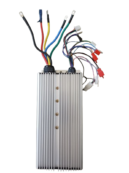
The Thripple 9 85A Motor Controller is an advanced electronic device designed to manage the operation of motors by controlling their speed, direction, and torque. This motor controller is versatile and can be used in a wide range of applications, including robotics, industrial automation, electric vehicles, and other motor-driven systems. Its robust design ensures reliable performance, making it suitable for both hobbyist and professional projects.
Explore Projects Built with motor controller

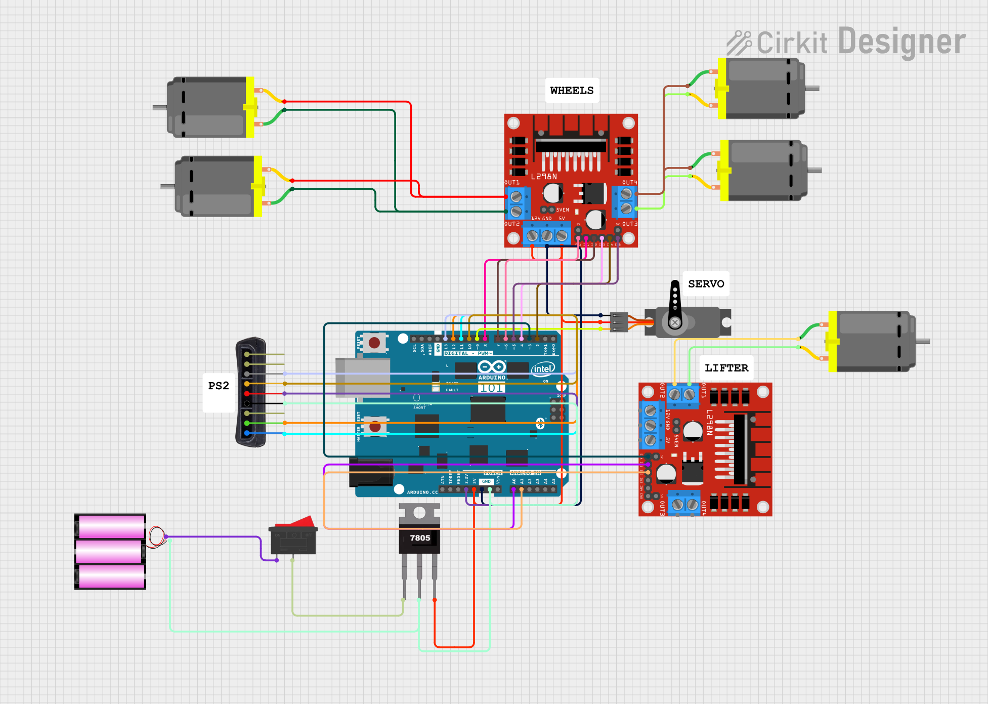
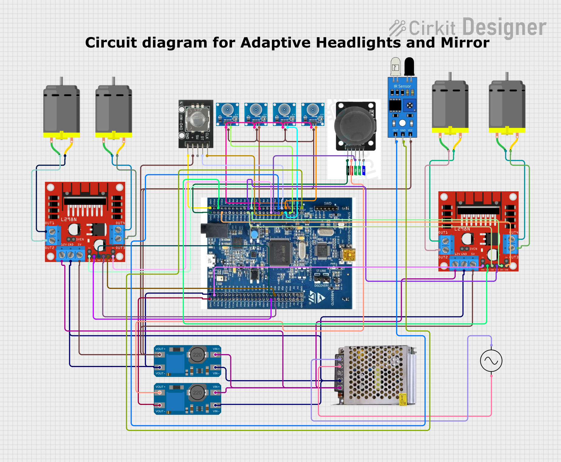
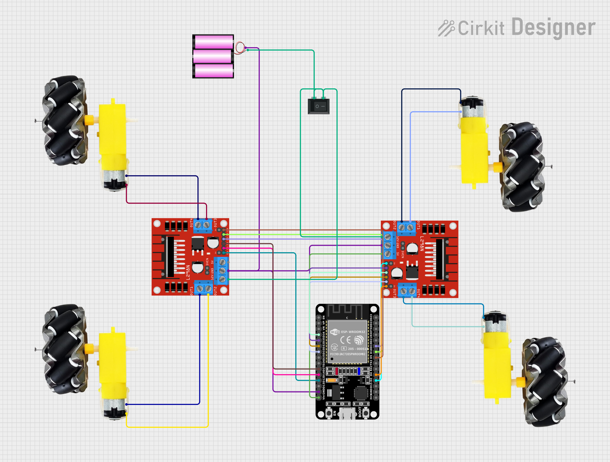
Explore Projects Built with motor controller
Common Applications
- Robotics: Controlling the movement of robotic arms, wheels, or tracks.
- Electric Vehicles: Managing motor speed and direction in e-bikes, scooters, and cars.
- Industrial Automation: Driving conveyor belts, pumps, and other machinery.
- DIY Projects: Powering small motors in custom electronics projects.
Technical Specifications
The Thripple 9 85A Motor Controller is designed to handle a variety of motor types, including brushed DC motors and brushless DC motors. Below are the key technical details:
General Specifications
| Parameter | Value |
|---|---|
| Manufacturer | Thripple 9 |
| Part ID | 85A |
| Motor Type Supported | Brushed DC, Brushless DC |
| Input Voltage Range | 6V to 36V |
| Continuous Current | 85A |
| Peak Current | 120A |
| PWM Frequency | 20 kHz |
| Control Interface | PWM, UART, Analog Input |
| Operating Temperature | -20°C to 85°C |
| Dimensions | 100mm x 60mm x 25mm |
| Weight | 150g |
Pin Configuration
The motor controller features a set of pins for power, motor connections, and control signals. Below is the pinout description:
| Pin Number | Name | Description |
|---|---|---|
| 1 | VIN+ | Positive input voltage terminal (6V to 36V). |
| 2 | VIN- | Negative input voltage terminal (ground). |
| 3 | M+ | Positive terminal for motor connection. |
| 4 | M- | Negative terminal for motor connection. |
| 5 | PWM | Pulse Width Modulation input for speed control. |
| 6 | DIR | Direction control input (logic HIGH for forward, LOW for reverse). |
| 7 | EN | Enable pin (logic HIGH to enable the motor controller). |
| 8 | UART_RX | UART receive pin for serial communication. |
| 9 | UART_TX | UART transmit pin for serial communication. |
| 10 | GND | Ground connection for control signals. |
Usage Instructions
How to Use the Motor Controller in a Circuit
- Power Supply: Connect a DC power supply (6V to 36V) to the
VIN+andVIN-pins. Ensure the power supply can handle the current requirements of your motor. - Motor Connection: Connect the motor terminals to the
M+andM-pins. Double-check the polarity for proper operation. - Control Signals:
- For speed control, provide a PWM signal (0% to 100% duty cycle) to the
PWMpin. - To control the motor's direction, set the
DIRpin to HIGH (forward) or LOW (reverse). - Use the
ENpin to enable or disable the motor controller.
- For speed control, provide a PWM signal (0% to 100% duty cycle) to the
- Optional UART Communication: Connect the
UART_RXandUART_TXpins to a microcontroller or computer for advanced control and monitoring.
Important Considerations
- Heat Dissipation: The motor controller may generate heat during operation. Use a heatsink or active cooling if operating at high currents for extended periods.
- Current Limiting: Ensure the motor's current draw does not exceed the controller's continuous current rating (85A).
- Wiring: Use appropriately rated wires for power and motor connections to prevent overheating or voltage drops.
- Safety: Always disconnect power before making any wiring changes.
Example: Using with Arduino UNO
Below is an example of how to control the motor controller using an Arduino UNO:
// Thripple 9 85A Motor Controller Example
// This code demonstrates basic motor speed and direction control using PWM and DIR pins.

#define PWM_PIN 9  // Connect to the PWM pin on the motor controller
#define DIR_PIN 8  // Connect to the DIR pin on the motor controller
#define EN_PIN 7   // Connect to the EN pin on the motor controller

void setup() {
  pinMode(PWM_PIN, OUTPUT); // Set PWM pin as output
  pinMode(DIR_PIN, OUTPUT); // Set DIR pin as output
  pinMode(EN_PIN, OUTPUT);  // Set EN pin as output

  digitalWrite(EN_PIN, HIGH); // Enable the motor controller
}

void loop() {
  // Set motor direction to forward
  digitalWrite(DIR_PIN, HIGH);

  // Gradually increase motor speed
  for (int speed = 0; speed <= 255; speed++) {
    analogWrite(PWM_PIN, speed); // Set PWM duty cycle (0-255)
    delay(20); // Wait 20ms
  }

  delay(1000); // Run at full speed for 1 second

  // Set motor direction to reverse
  digitalWrite(DIR_PIN, LOW);

  // Gradually decrease motor speed
  for (int speed = 255; speed >= 0; speed--) {
    analogWrite(PWM_PIN, speed); // Set PWM duty cycle (0-255)
    delay(20); // Wait 20ms
  }

  delay(1000); // Wait for 1 second before repeating
}
Troubleshooting and FAQs
Common Issues
Motor Not Running:
- Ensure the
ENpin is set to HIGH. - Verify the power supply voltage and current ratings.
- Check all wiring connections for proper contact.
- Ensure the
Motor Running in the Wrong Direction:
- Reverse the logic level on the
DIRpin. - Verify the motor wiring polarity.
- Reverse the logic level on the
Overheating:
- Ensure proper ventilation or use a heatsink.
- Check that the motor's current draw does not exceed the controller's rating.
PWM Signal Not Working:
- Verify the PWM signal frequency (should be compatible with the controller's 20 kHz frequency).
- Check the Arduino code for errors.
FAQs
Q: Can I use this motor controller with a brushless DC motor?
A: Yes, the Thripple 9 85A Motor Controller supports both brushed and brushless DC motors. However, additional configuration may be required for brushless motors.
Q: What happens if the input voltage exceeds 36V?
A: Exceeding the maximum input voltage can damage the motor controller. Always use a power supply within the specified range (6V to 36V).
Q: Can I control the motor controller using a Raspberry Pi?
A: Yes, you can use the Raspberry Pi's GPIO pins to send PWM and direction signals to the motor controller. Ensure proper voltage level shifting if needed.
Q: Is reverse polarity protection included?
A: No, the motor controller does not include reverse polarity protection. Double-check your wiring to avoid damage.
This concludes the documentation for the Thripple 9 85A Motor Controller. For further assistance, refer to the manufacturer's support resources.