
How to Use QuinLED Dig Next 2: Examples, Pinouts, and Specs
 Design with QuinLED Dig Next 2 in Cirkit Designer
Introduction
The QuinLED Dig Next 2 (Manufacturer Part ID: Dig-Next-2) is a versatile LED controller designed for addressable RGB LED strips. Manufactured by QuinLED, this component offers advanced features for controlling LED lighting, making it ideal for both hobbyists and professional lighting installations. It supports multiple control modes, integrates seamlessly with various smart home systems, and provides robust performance for a wide range of applications.
Explore Projects Built with QuinLED Dig Next 2
 Open Project in Cirkit Designer
 Open Project in Cirkit Designer
 Open Project in Cirkit Designer
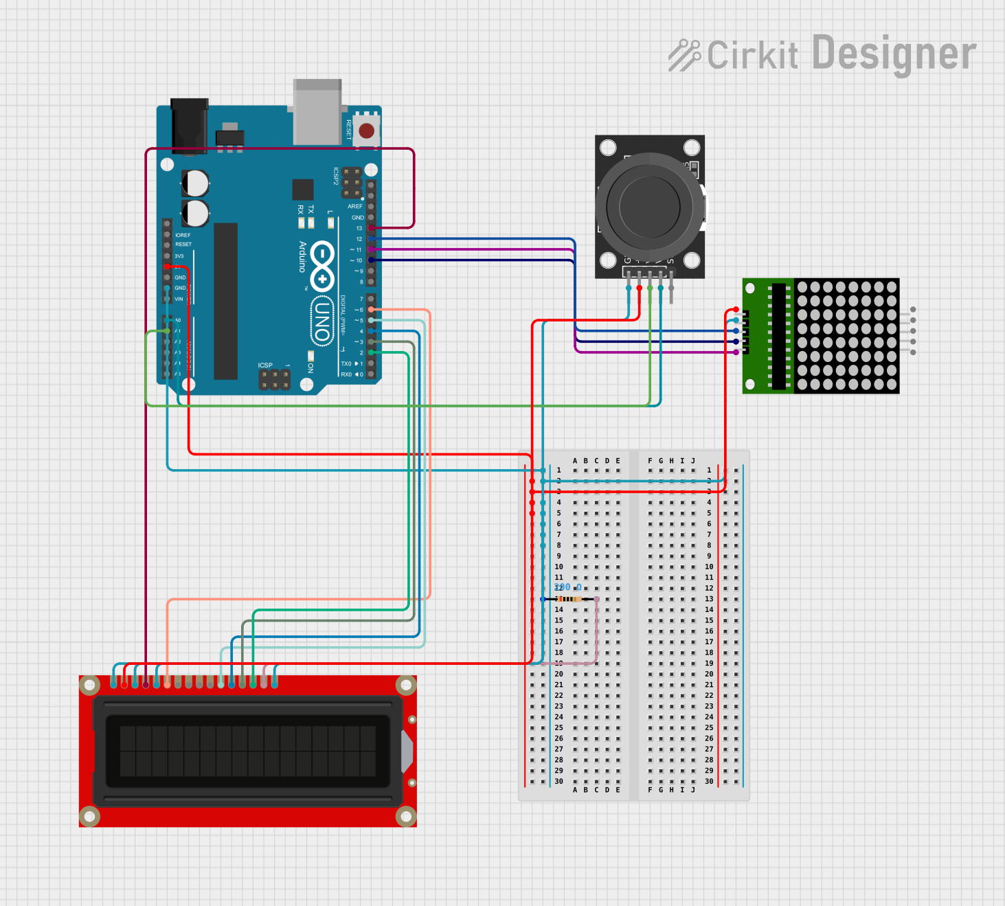 Open Project in Cirkit Designer
Explore Projects Built with QuinLED Dig Next 2
Open Project in Cirkit DesignerOpen Project in Cirkit DesignerOpen Project in Cirkit DesignerOpen Project in Cirkit DesignerCommon Applications and Use Cases
- Smart home lighting systems
- Decorative and ambient lighting
- Stage and event lighting
- Custom RGB lighting projects
- Integration with platforms like Home Assistant, WLED, and more
Technical Specifications
Key Technical Details
| Parameter | Specification |
|---|---|
| Input Voltage Range | 5V to 24V DC |
| Maximum Current Output | 15A (dependent on power supply) |
| Supported LED Protocols | WS2812, WS2813, SK6812, APA102, etc. |
| Control Interfaces | Wi-Fi (ESP32-based), GPIO |
| Number of LED Channels | 2 independent channels |
| Operating Temperature | -20°C to 60°C |
| Dimensions | 50mm x 50mm x 15mm |
Pin Configuration and Descriptions
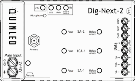
The QuinLED Dig Next 2 features a straightforward pin layout for easy integration into your projects. Below is the pin configuration:
| Pin Name | Description |
|---|---|
| VIN | Power input (5V to 24V DC) |
| GND | Ground connection |
| DATA1 | Data output for Channel 1 (connect to the data line of the first LED strip) |
| DATA2 | Data output for Channel 2 (optional second LED strip) |
| GPIO Pins | General-purpose input/output pins for custom configurations |
| Reset Button | Resets the controller |
| Wi-Fi Antenna | Built-in antenna for wireless communication |
Usage Instructions
How to Use the Component in a Circuit
- Power Supply: Connect a DC power supply (5V to 24V) to the VIN and GND pins. Ensure the power supply can handle the current requirements of your LED strips.
- LED Strip Connection:
- Connect the data line of your addressable LED strip to the DATA1 pin.
- Optionally, connect a second LED strip to the DATA2 pin for dual-channel operation.
- Wi-Fi Configuration: Use the built-in ESP32 module to configure the controller via Wi-Fi. This can be done using software like WLED or custom firmware.
- Smart Home Integration: Pair the controller with platforms like Home Assistant for advanced automation and control.
Important Considerations and Best Practices
- Power Supply Selection: Always use a power supply that matches the voltage of your LED strip and provides sufficient current.
- Data Line Resistor: Add a 330Ω resistor in series with the data line to protect the LEDs from voltage spikes.
- Capacitor: Place a 1000µF capacitor across the VIN and GND pins to stabilize the power supply.
- Heat Management: Ensure proper ventilation or cooling if operating at high currents for extended periods.
- Firmware Updates: Regularly update the firmware (e.g., WLED) to access new features and bug fixes.
Example Code for Arduino UNO
Although the QuinLED Dig Next 2 is primarily ESP32-based, you can control addressable LEDs with an Arduino UNO for testing purposes. Below is an example using the FastLED library:
#include <FastLED.h>

// Define the number of LEDs and the data pin
#define NUM_LEDS 60
#define DATA_PIN 6

// Create an array to hold the LED data
CRGB leds[NUM_LEDS];

void setup() {
  // Initialize the LED strip
  FastLED.addLeds<WS2812, DATA_PIN, GRB>(leds, NUM_LEDS);
  FastLED.clear(); // Clear all LEDs
  FastLED.show();  // Update the LEDs
}

void loop() {
  // Example: Set all LEDs to red
  for (int i = 0; i < NUM_LEDS; i++) {
    leds[i] = CRGB::Red; // Set each LED to red
  }
  FastLED.show(); // Update the LEDs with the new color
  delay(1000);    // Wait for 1 second

  // Example: Turn off all LEDs
  FastLED.clear(); // Clear all LEDs
  FastLED.show();  // Update the LEDs
  delay(1000);     // Wait for 1 second
}
Troubleshooting and FAQs
Common Issues and Solutions
LEDs Not Lighting Up:
- Verify the power supply is connected and providing the correct voltage.
- Check the data line connection and ensure it is properly soldered or secured.
- Ensure the LED strip is compatible with the supported protocols (e.g., WS2812, SK6812).
Flickering LEDs:
- Add a 330Ω resistor in series with the data line to reduce noise.
- Use a capacitor (1000µF) across the power input to stabilize the voltage.
- Ensure the power supply can handle the current draw of the LEDs.
Wi-Fi Connection Issues:
- Ensure the controller is within range of your Wi-Fi network.
- Reset the controller and reconfigure the Wi-Fi settings.
- Update the firmware to the latest version.
Overheating:
- Reduce the brightness of the LEDs to lower the current draw.
- Ensure proper ventilation or add a heatsink if necessary.
FAQs
Q: Can I use the QuinLED Dig Next 2 with non-addressable LED strips?
A: No, the QuinLED Dig Next 2 is specifically designed for addressable LED strips that use protocols like WS2812, SK6812, and APA102.
Q: How many LEDs can I control with this controller?
A: The maximum number of LEDs depends on the power supply and the memory of the ESP32. Typically, you can control up to 1000 LEDs per channel.
Q: Is the controller compatible with 12V LED strips?
A: Yes, the controller supports LED strips with voltages between 5V and 24V. Ensure the power supply matches the LED strip voltage.
Q: Can I use this controller outdoors?
A: The QuinLED Dig Next 2 is not waterproof. If using outdoors, enclose it in a weatherproof housing.