Cirkit Designer Logo
Cirkit Designer
Your all-in-one circuit design IDE
Home / 
Component Documentation

How to Use MAX30102: Examples, Pinouts, and Specs

Image of MAX30102
Cirkit Designer LogoDesign with MAX30102 in Cirkit Designer

Introduction

The MAX30102 Heart Rate and Pulse Oximetry Sensor Module, manufactured by Analog Devices, is a highly integrated optical sensor designed for non-invasive health monitoring. It uses photoplethysmography (PPG) to measure blood oxygen saturation (SpO2) and heart rate. The module combines an LED driver, photodetector, and analog signal processing in a compact form factor, making it ideal for wearable devices, fitness trackers, and medical monitoring systems.

Explore Projects Built with MAX30102

Use Cirkit Designer to design, explore, and prototype these projects online. Some projects support real-time simulation. Click "Open Project" to start designing instantly!
Battery-Powered Health Monitoring System with Nucleo WB55RG and OLED Display
Image of Pulsefex: A project utilizing MAX30102 in a practical application
This circuit is a multi-sensor data acquisition system that uses a Nucleo WB55RG microcontroller to interface with a digital temperature sensor (TMP102), a pulse oximeter and heart-rate sensor (MAX30102), and a 0.96" OLED display via I2C. Additionally, it includes a Sim800l module for GSM communication, powered by a 3.7V LiPo battery.
Cirkit Designer LogoOpen Project in Cirkit Designer
ESP32-Based Multi-Sensor Health Monitoring System with Bluetooth Connectivity
Image of circuit diagram: A project utilizing MAX30102 in a practical application
This circuit features an ESP32-WROOM-32UE microcontroller as the central processing unit, interfacing with a variety of sensors and modules. It includes a MAX30100 pulse oximeter and heart-rate sensor, an MLX90614 infrared thermometer, an HC-05 Bluetooth module for wireless communication, and a Neo 6M GPS module for location tracking. All components are powered by a common voltage supply and are connected to specific GPIO pins on the ESP32 for data exchange, with the sensors using I2C communication and the modules using UART.
Cirkit Designer LogoOpen Project in Cirkit Designer
ESP32 and MAX30100 Pulse Oximeter
Image of t: A project utilizing MAX30102 in a practical application
This circuit features an ESP32 microcontroller connected to a MAX30100 sensor, which is likely used for measuring pulse oximetry. The ESP32 is interfaced with the MAX30100 via I2C communication, as indicated by the SDA and SCL connections. Power is supplied to both the ESP32 and the MAX30100 by a 5V battery, with common ground established across the components.
Cirkit Designer LogoOpen Project in Cirkit Designer
ESP32-Based Health Monitoring System with Bluetooth and GPS
Image of circuit diagram: A project utilizing MAX30102 in a practical application
This circuit integrates an ESP32 microcontroller with various sensors and modules, including a MAX30100 pulse oximeter, an MLX90614 infrared thermometer, a Neo 6M GPS module, and an HC-05 Bluetooth module. The ESP32 collects data from these sensors and modules via I2C and UART interfaces, enabling wireless communication and GPS tracking capabilities.
Cirkit Designer LogoOpen Project in Cirkit Designer

Explore Projects Built with MAX30102

Use Cirkit Designer to design, explore, and prototype these projects online. Some projects support real-time simulation. Click "Open Project" to start designing instantly!
Image of Pulsefex: A project utilizing MAX30102 in a practical application
Battery-Powered Health Monitoring System with Nucleo WB55RG and OLED Display
This circuit is a multi-sensor data acquisition system that uses a Nucleo WB55RG microcontroller to interface with a digital temperature sensor (TMP102), a pulse oximeter and heart-rate sensor (MAX30102), and a 0.96" OLED display via I2C. Additionally, it includes a Sim800l module for GSM communication, powered by a 3.7V LiPo battery.
Cirkit Designer LogoOpen Project in Cirkit Designer
Image of circuit diagram: A project utilizing MAX30102 in a practical application
ESP32-Based Multi-Sensor Health Monitoring System with Bluetooth Connectivity
This circuit features an ESP32-WROOM-32UE microcontroller as the central processing unit, interfacing with a variety of sensors and modules. It includes a MAX30100 pulse oximeter and heart-rate sensor, an MLX90614 infrared thermometer, an HC-05 Bluetooth module for wireless communication, and a Neo 6M GPS module for location tracking. All components are powered by a common voltage supply and are connected to specific GPIO pins on the ESP32 for data exchange, with the sensors using I2C communication and the modules using UART.
Cirkit Designer LogoOpen Project in Cirkit Designer
Image of t: A project utilizing MAX30102 in a practical application
ESP32 and MAX30100 Pulse Oximeter
This circuit features an ESP32 microcontroller connected to a MAX30100 sensor, which is likely used for measuring pulse oximetry. The ESP32 is interfaced with the MAX30100 via I2C communication, as indicated by the SDA and SCL connections. Power is supplied to both the ESP32 and the MAX30100 by a 5V battery, with common ground established across the components.
Cirkit Designer LogoOpen Project in Cirkit Designer
Image of circuit diagram: A project utilizing MAX30102 in a practical application
ESP32-Based Health Monitoring System with Bluetooth and GPS
This circuit integrates an ESP32 microcontroller with various sensors and modules, including a MAX30100 pulse oximeter, an MLX90614 infrared thermometer, a Neo 6M GPS module, and an HC-05 Bluetooth module. The ESP32 collects data from these sensors and modules via I2C and UART interfaces, enabling wireless communication and GPS tracking capabilities.
Cirkit Designer LogoOpen Project in Cirkit Designer

Common Applications

  • Wearable health monitoring devices
  • Fitness trackers
  • Medical-grade pulse oximeters
  • Remote patient monitoring systems
  • IoT-based health solutions

Technical Specifications

The MAX30102 is designed for low-power operation and high accuracy. Below are its key technical details:

Key Specifications

Parameter Value
Supply Voltage 1.8V (core) and 3.3V (LED driver)
Operating Current 600 µA (typical)
Standby Current 0.7 µA
LED Wavelengths Red: 660 nm, IR: 880 nm
Communication Interface I²C (up to 400 kHz)
Operating Temperature Range -40°C to +85°C
Dimensions 5.6 mm x 3.3 mm x 1.55 mm

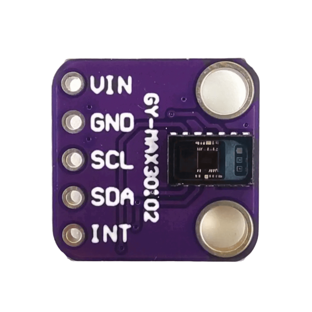
Pin Configuration and Descriptions

The MAX30102 module typically comes with the following pinout:

Pin Name Pin Number Description
VIN 1 Power supply input (3.3V)
GND 2 Ground
SDA 3 I²C data line
SCL 4 I²C clock line
INT 5 Interrupt output (active low)

Usage Instructions

The MAX30102 is straightforward to use in a circuit, especially with microcontrollers like the Arduino UNO. Below are the steps to integrate and use the sensor:

Circuit Connection

  1. Power Supply: Connect the VIN pin to a 3.3V power source and the GND pin to ground.
  2. I²C Communication: Connect the SDA and SCL pins to the corresponding I²C pins on your microcontroller (e.g., A4 and A5 on Arduino UNO).
  3. Interrupt Pin: Optionally, connect the INT pin to a digital input pin on the microcontroller to handle interrupts.

Important Considerations

  • Use pull-up resistors (typically 4.7 kΩ) on the SDA and SCL lines if not already included on the module.
  • Ensure the sensor is placed in contact with the skin for accurate readings.
  • Avoid direct exposure to ambient light, as it may interfere with measurements.

Sample Arduino Code

Below is an example of how to use the MAX30102 with an Arduino UNO to read heart rate and SpO2 data. This code uses the SparkFun MAX3010x library.

#include <Wire.h>
#include "MAX30105.h" // Include the MAX3010x library

MAX30105 particleSensor; // Create an instance of the sensor

void setup() {
  Serial.begin(9600); // Initialize serial communication
  Serial.println("Initializing MAX30102...");

  // Initialize the sensor
  if (!particleSensor.begin()) {
    Serial.println("MAX30102 not detected. Check connections.");
    while (1); // Halt execution if the sensor is not found
  }

  // Configure the sensor
  particleSensor.setup(); // Use default settings
  particleSensor.setPulseAmplitudeRed(0x0A); // Set red LED brightness
  particleSensor.setPulseAmplitudeIR(0x0A);  // Set IR LED brightness
}

void loop() {
  // Read data from the sensor
  long redValue = particleSensor.getRed(); // Get red light reading
  long irValue = particleSensor.getIR();   // Get IR light reading

  // Print the readings to the serial monitor
  Serial.print("Red: ");
  Serial.print(redValue);
  Serial.print(" IR: ");
  Serial.println(irValue);

  delay(100); // Wait 100 ms before the next reading
}

Best Practices

  • Calibrate the sensor for your specific application to improve accuracy.
  • Use a low-noise power supply to minimize interference.
  • Place the sensor on a stable surface or secure it to the skin to reduce motion artifacts.

Troubleshooting and FAQs

Common Issues and Solutions

Issue Possible Cause Solution
No data from the sensor Incorrect wiring or loose connections Verify all connections and pin mappings.
Inaccurate readings Ambient light interference Shield the sensor from external light.
Sensor not detected on I²C bus Incorrect I²C address or wiring issue Ensure the I²C address is correct (0x57).
High noise in readings Motion artifacts or unstable placement Secure the sensor and minimize movement.

FAQs

  1. What is the default I²C address of the MAX30102?
    The default I²C address is 0x57.

  2. Can the MAX30102 measure SpO2 and heart rate simultaneously?
    Yes, the sensor can measure both parameters simultaneously using its dual LED system.

  3. What is the maximum sampling rate of the MAX30102?
    The sensor supports sampling rates up to 3200 samples per second.

  4. Is the MAX30102 suitable for medical-grade applications?
    While the MAX30102 is highly accurate, it is not certified for medical-grade applications without additional validation.

By following this documentation, users can effectively integrate and utilize the MAX30102 for health monitoring applications.